I ended up with an interesting little VHF low band transceiver made by Tadiran:
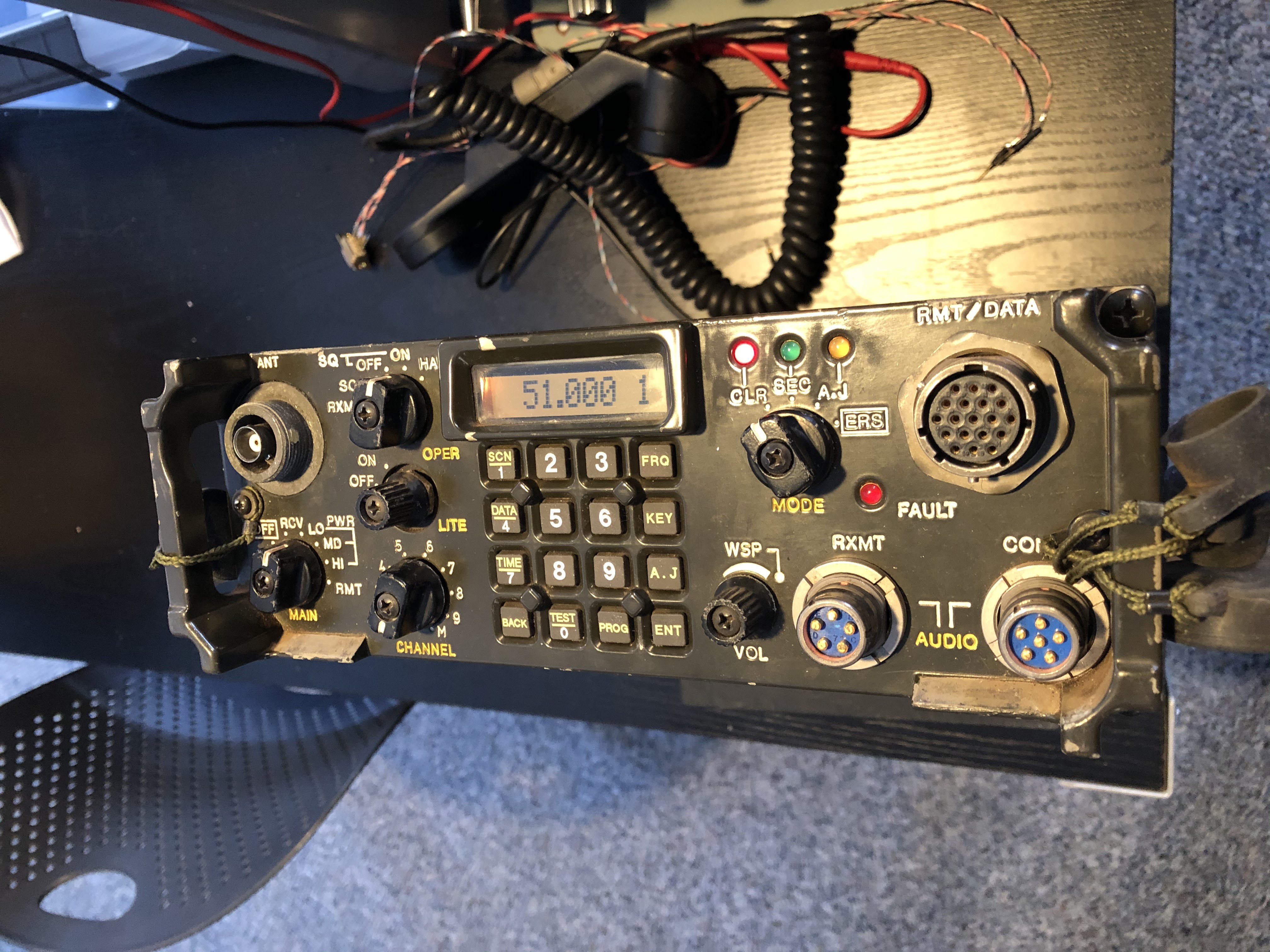
The frequency range is 30.000 to 87.975 MHz, FM wide or narrow band.
The radio seems to operate as intended.
But it’s boring to have it only cover the 6 meter band. I wonder if it can be made to go down into the 10 meter band? The first step would be to change the lower frequency limit in firmware from 30 to 28 MHz.
So I opened it up and looked for the control processor. Found this:
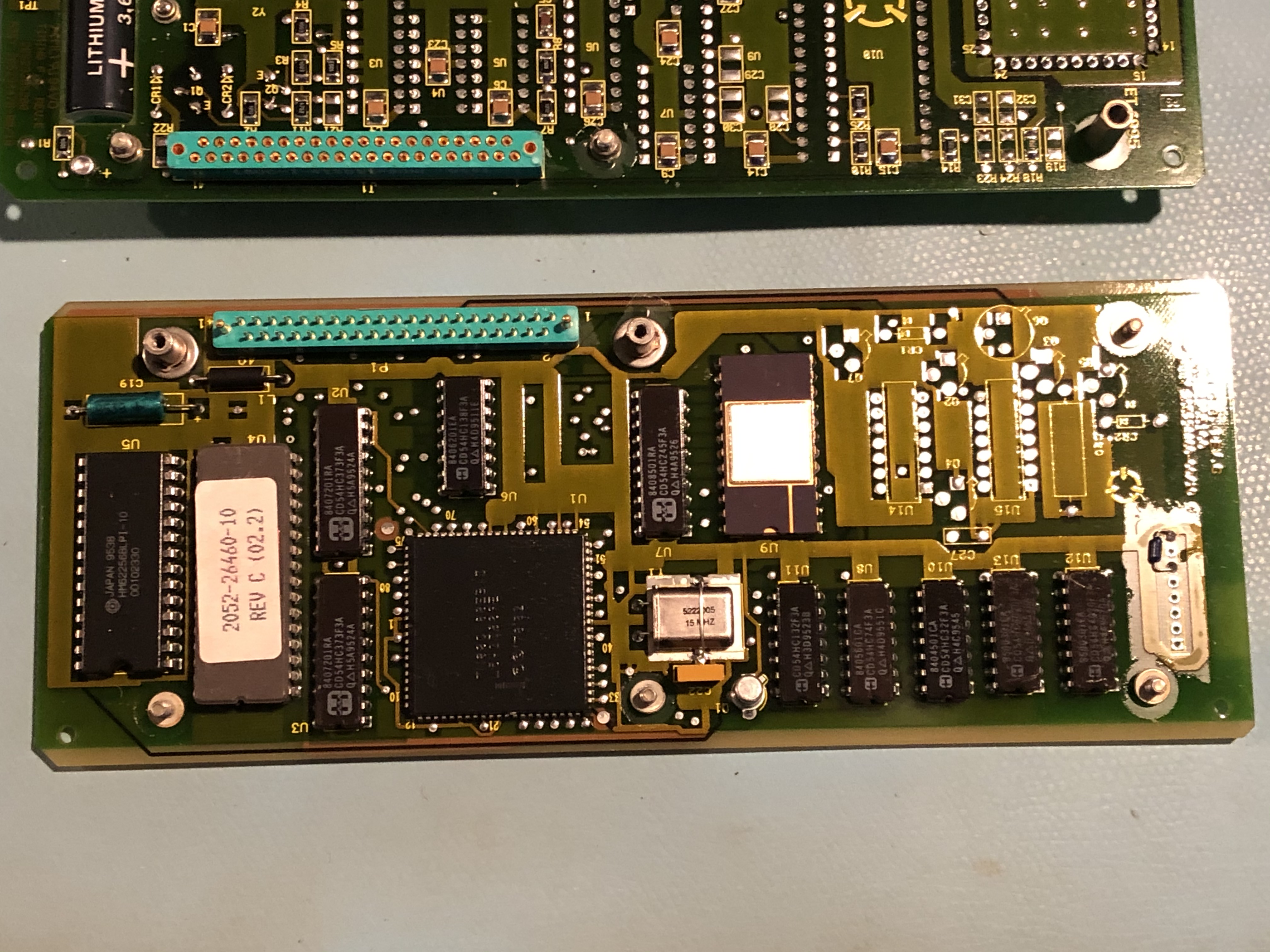
Processor is a 80C188EB. Like the PRC-2200 made by Tadiran, the EPROM chip only has the four corner pins soldered with the rest in mini sockets.
I removed the EPROM and read it on a programmer. Then I started analyzing using Ghidra. One of the first things I look for are ASCII messages. This can sometimes lead to hidden features. I did find a lot of strings, but very strangely there were long messages which looked like they were for some kind of debugging work.
Then going through the startup code I saw that the area where these messages were was in an area of ROM that wasn’t mapped as active! And there were no ASCII messages, like are seen in normal operation, anywhere in the EPROM! That’s when it dawned on me there may be another processor in this radio.
Sure enough, on another board I found this:
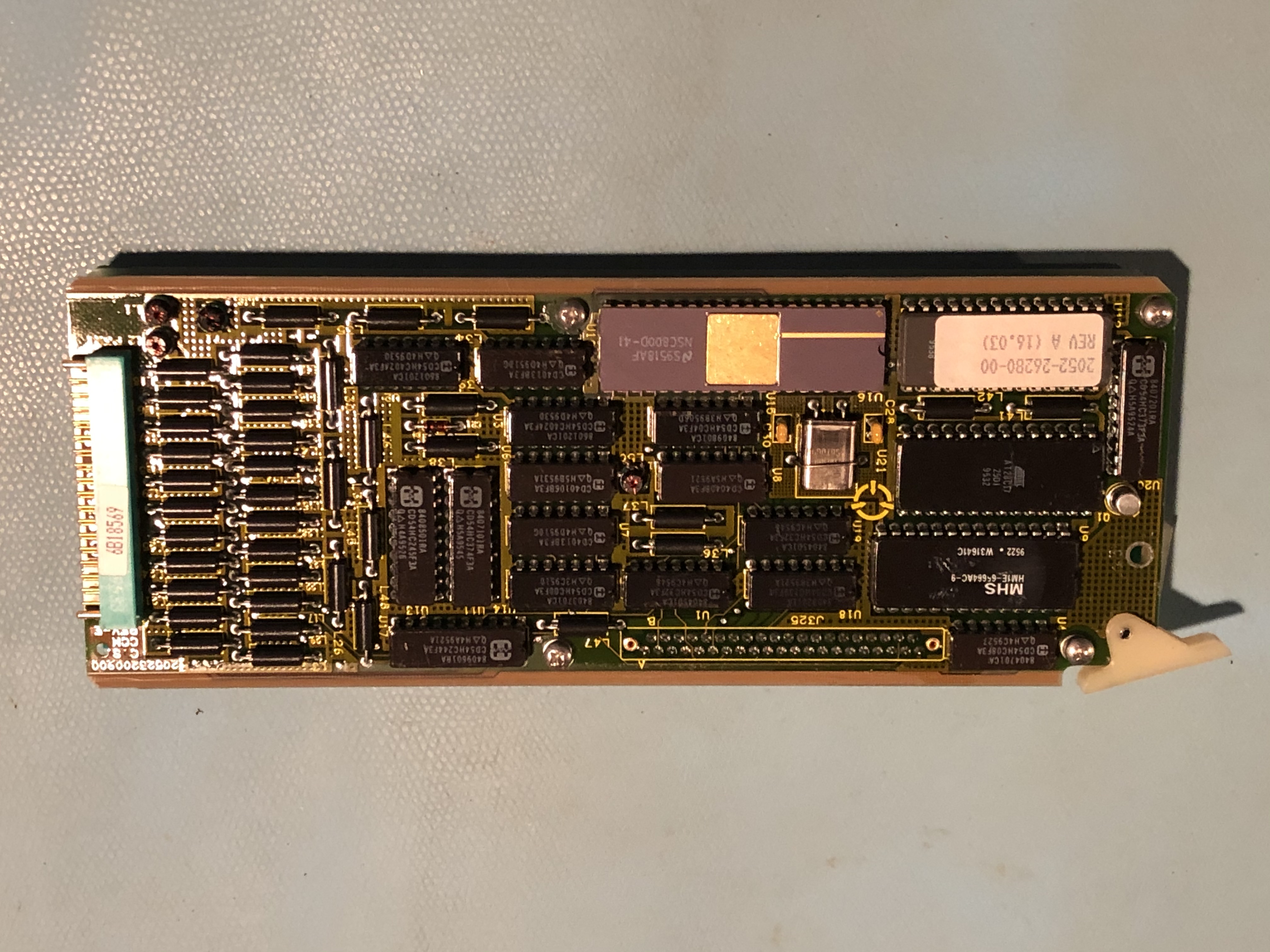
This one is a NSC800D, which is like a Z80. Same deal with the EPROM pins so I removed it and read it on a programmer. 27C512 part.
Loading into Ghidra showed all the messages you would see in normal radio operation so this is the correct processor to start my hacking with.
By the way, I found this in the code:
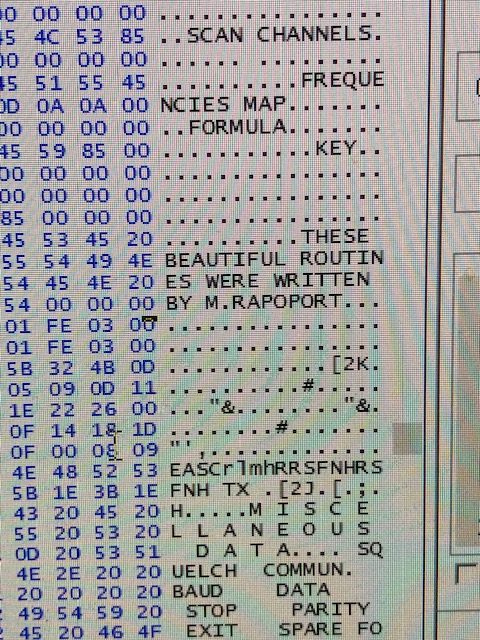
I was able to locate Michael Rapoport but he has not responded to my inquiries. I wanted to tell him I found his little comment.
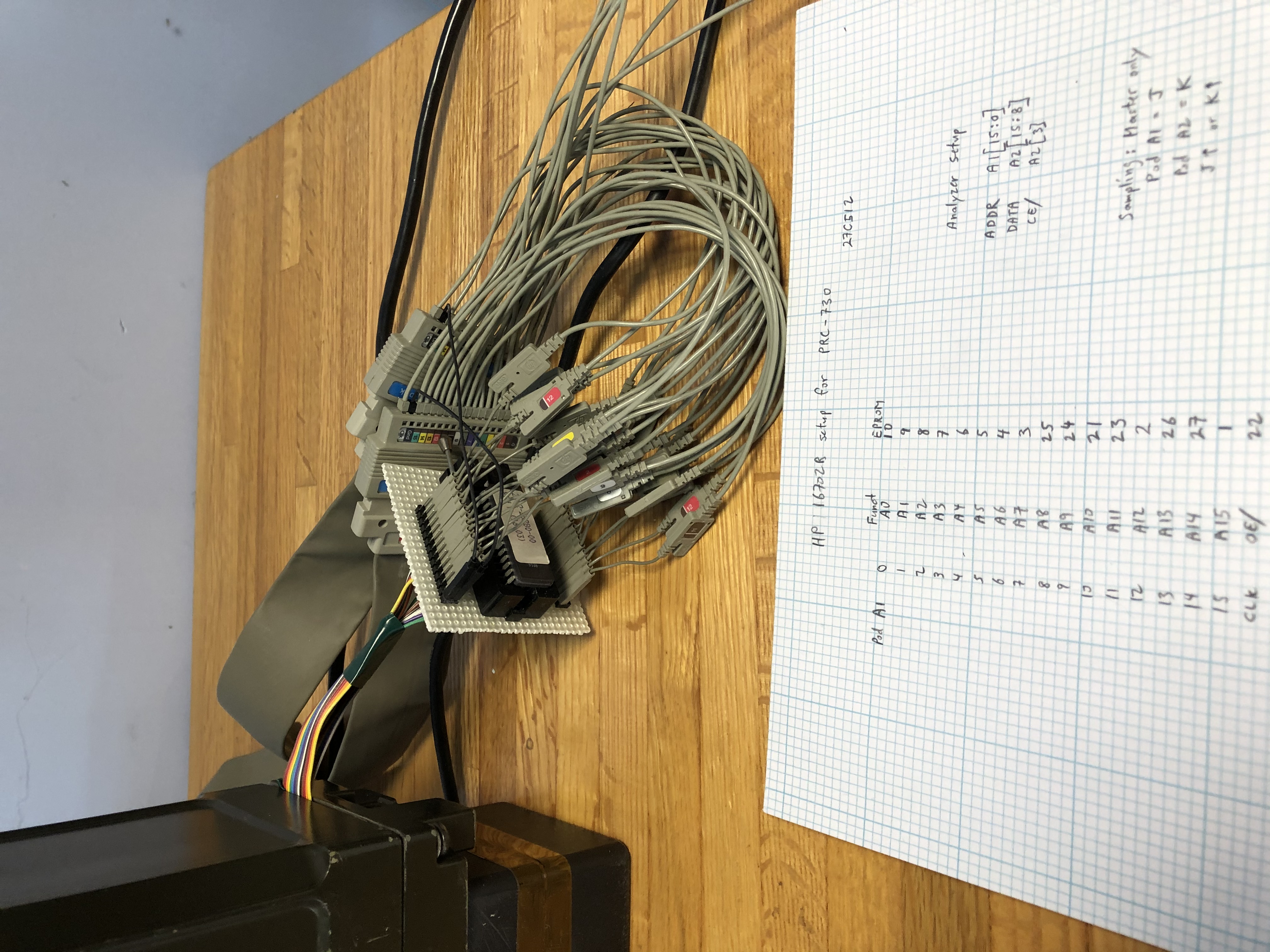
Even with Ghidra it is not easy to reverse engineer code so I like to trace code execution using a logic analyzer. I use a huge, noisy and heavy HP 16702B. It is an old beast but quite capable and was a steal at around $200 for analyzer and a bunch of cards and cables.
Hooking up to the microprocessor bus can be a challenge and I have worked out a quick hack which not only solves that but helps later on when I want to try different patches to the EPROM. I make an extender for the EPROM itself, like this:
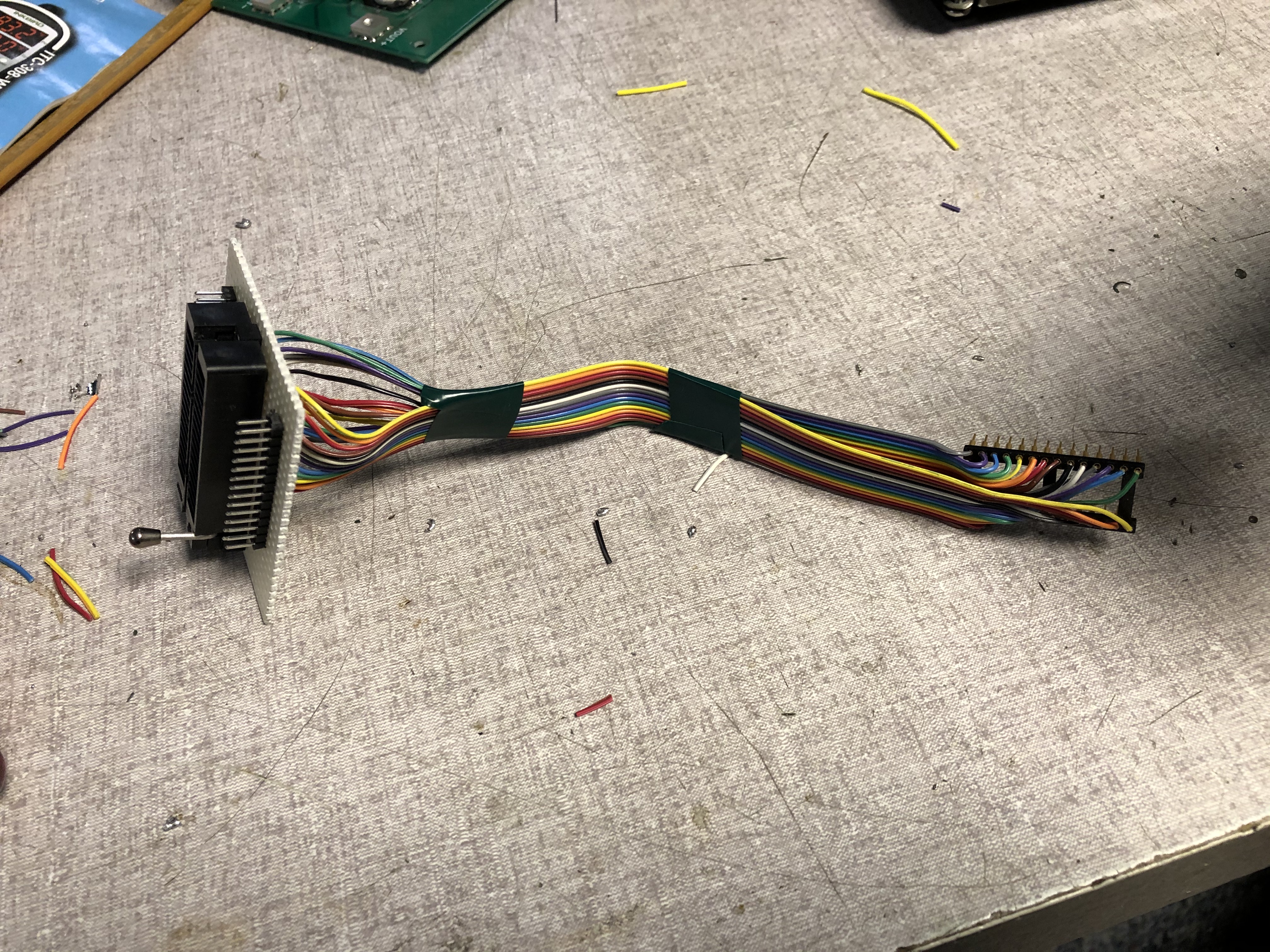
I use a ZIF socket so it is easy to put different chips in and 0.025″ headers wired to each pin for connecting the logic analyzer. Here’s how it looks once connected to the analyzer pods:
Now I can watch as code is executed. The analyzer setup looks like this:
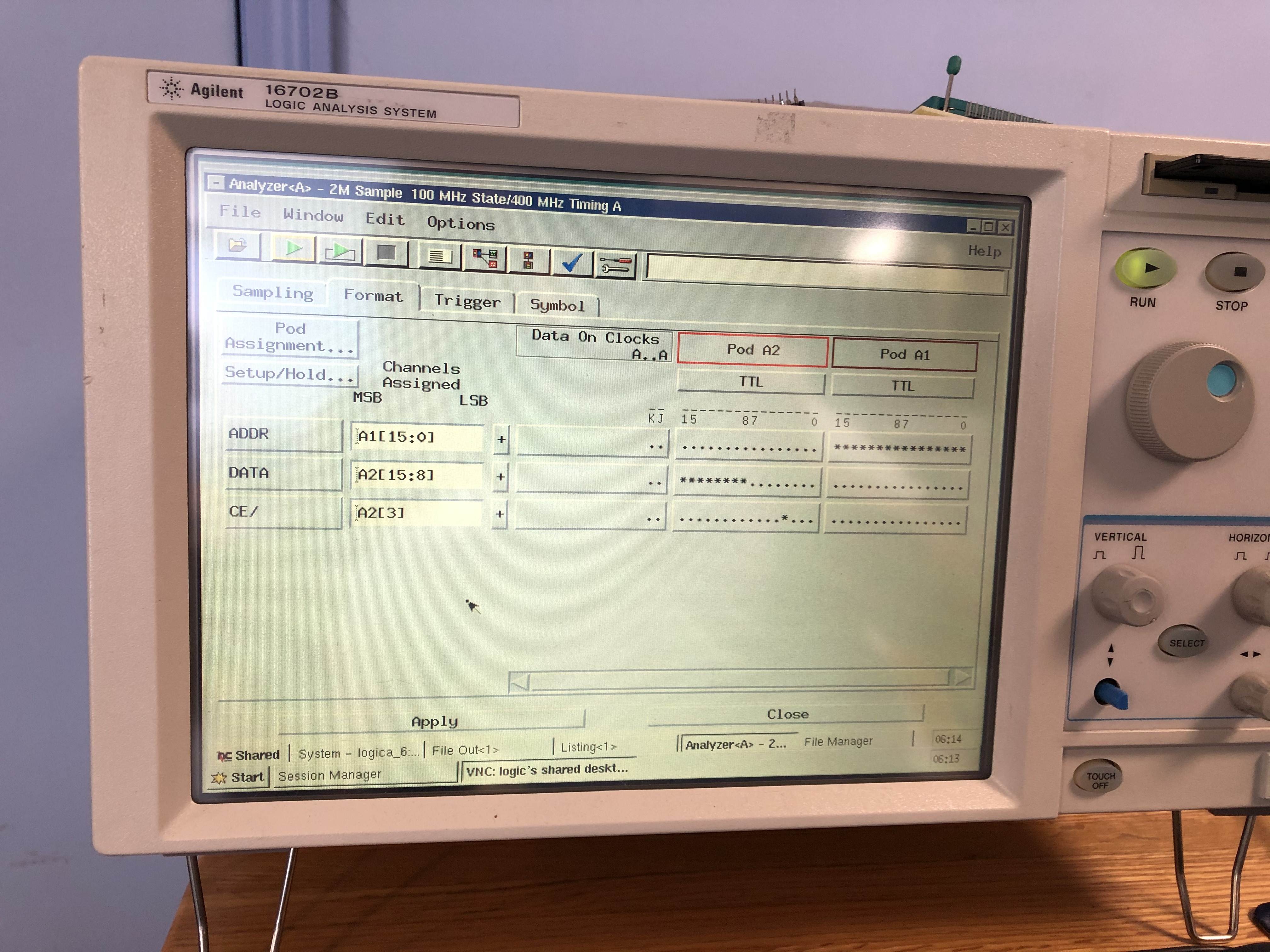
What I am doing is looking at the EPROM address and data lines and triggering each time the chip select goes inactive after being asserted. This shows me every EPROM read, whether code or data.
MY next step was to set trigger on seeing address 0000 as this is the processor reset vector. This will allow me to quickly find the EPROM checksum test and I will need to understand that before making any patches.
After that I found the address of the INV FREQ message which is displayed when I try to enter 28.0000 MHz. I set the analyzer to set the middle of its 2 million address read memory on the trigger of seeing address C15E which is the message. Note that the analyzer needs to be armed for capture AFTER the radio boot-up as otherwise the analyzer will trigger on the EPROM checksum routine scanning through.
Both captures were made and a quick look shows they make sense and are good.
The second trace is extremely useful in that it tells me many things:
- I now know where the routine to display messages is and how it works. This tells me how the display is addresses which helps fill out the hardware addressing puzzle.
- I can see how the message display routine is called especially the argument which is the message pointer. I can now backtrack to every place which calls this routine and by looking at the messages, I can get a good idea of what each section of code does.
- In this case, I can backtrack to the keypad entry routine and see how that is addressed. This is helpful to further solve the hardware interface puzzle and if I ever want to modify the keypad routine.
- And finally, this will lead me to where the 28.000 I entered was compared to the lower limit 0f 30.000 and rejected. Now it will be easy to change.
All for part 1 of this adventure. Analysis follows.
Peter