I guess time to post here rather than just on the Yahoo milpack group. This way it’s easier to find all the updates in one spot and in order.
The KY-67 is a very rugged VHF backpack transceiver covering the usual 30-88 MHz and made in the eighties. My impression was that it was made for an amphibious vehicle which experienced program delays so by the time the program went into production the radio’s technology and features were dated and not many were produced.
The unique part for the time was that the radio had integral digital encryption. Of course what this means is that for all radios which were surplussed the encryption boards had to be removed so every one of these anyone outside the military has seen is missing all those cards. While I commend the surplus disposition people for not just grinding the radio up to scrap, the removal of those boards renders the radio inoperational. Completely dead. Some have tried, but no word of anyone ever succeeding. Of course, the funny part is that I will likely only use this radio several times a year, and probably all on 51.0 MHz. But it looks really cool and rugged, like you could run over it with a truck. So I’m going to try and get it to run.
A kind soul offered me one with mounting base, unused, for the cost of shipping. Let the games begin, it against me.
Next post I’ll add some photos.
Here’s a summary of my progress to date:
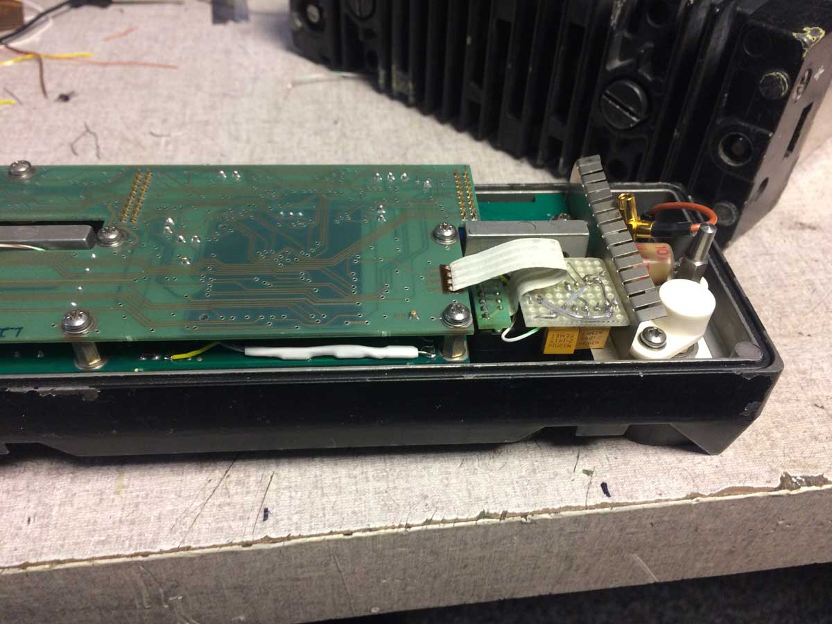
Two battery connectors for two 2590 type batteries. One runs the encryption boards, the other the radio itself.
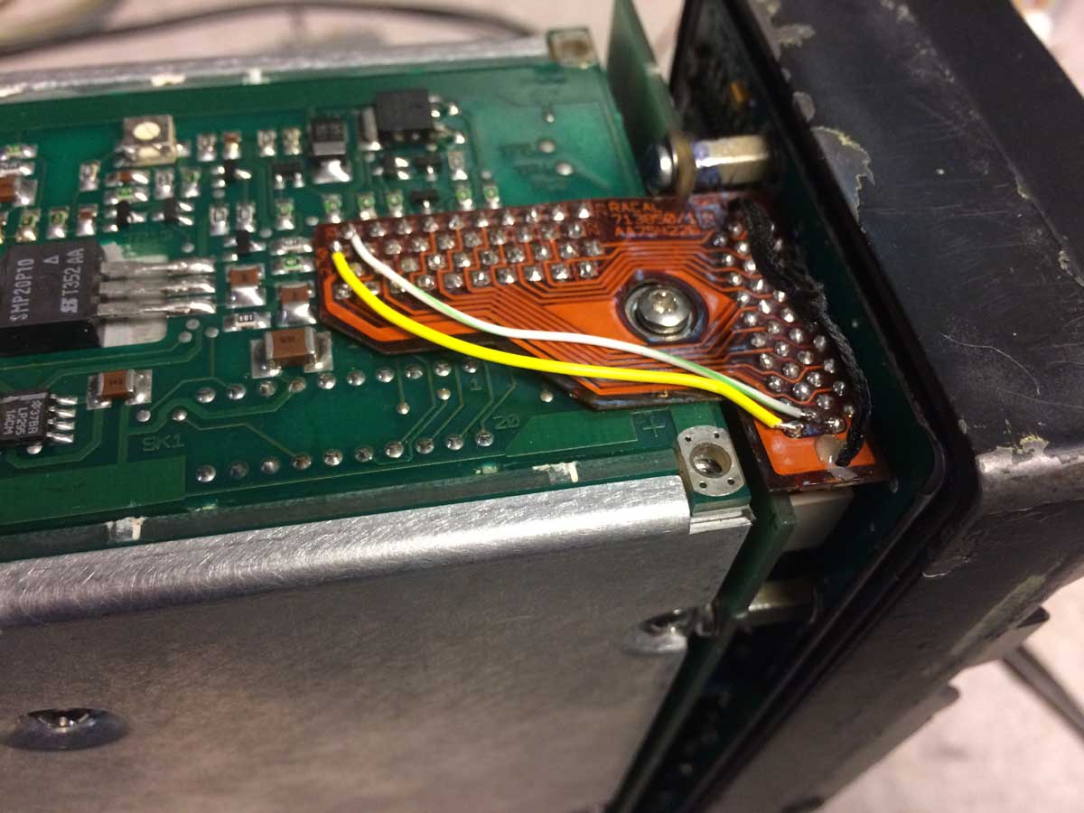
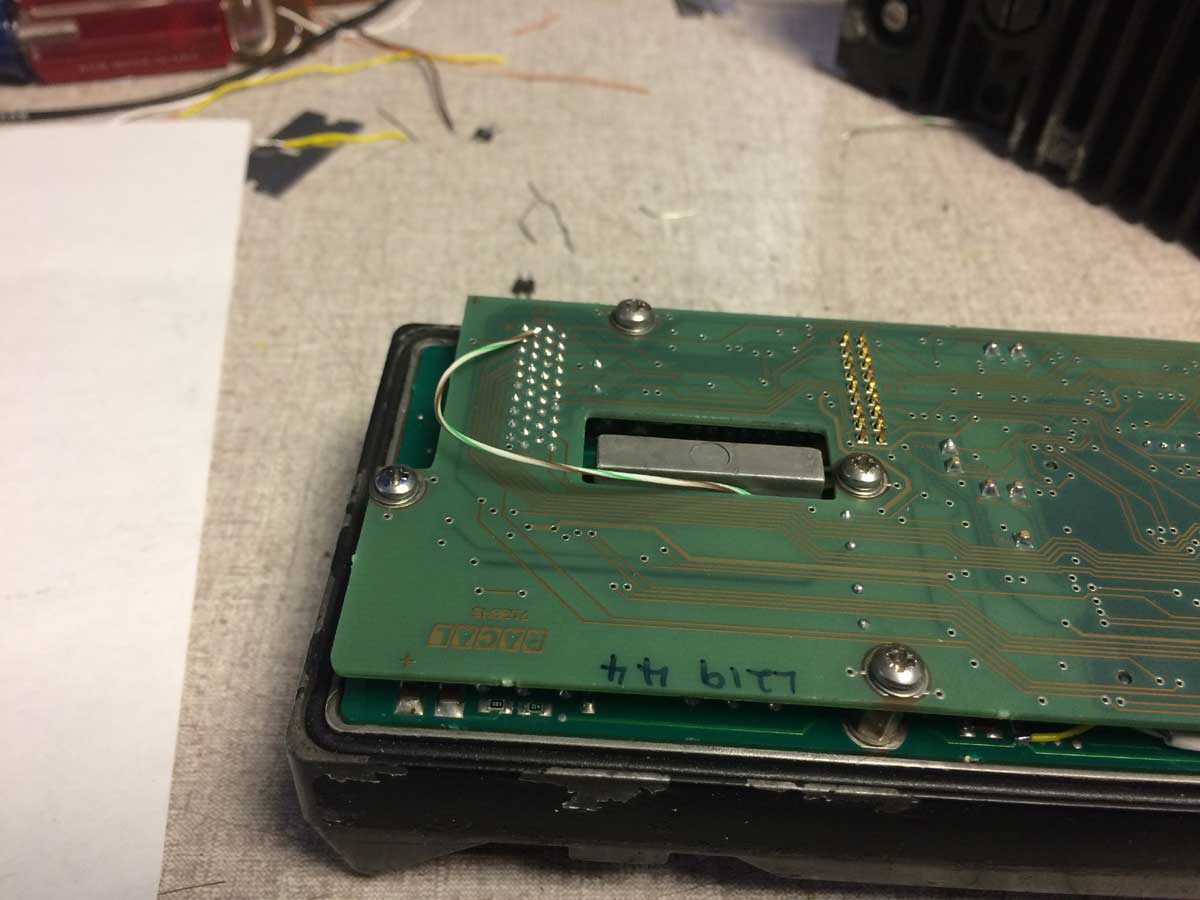
The CPU board operates the front panel display. I was worried it might be controlled by the missing cards. CPU is a NSC800, an extended temperature range Z80, Firmware was on a socketed (yay!) 27C256. Hmm, only 64k instructions at most, doable..
Read it out, ran some Z80 disassembler I found on the web, got this:
https://github.com/kb2vtl/KY-67
Look at the .asm file, that’s the one I’m annotating as I go.
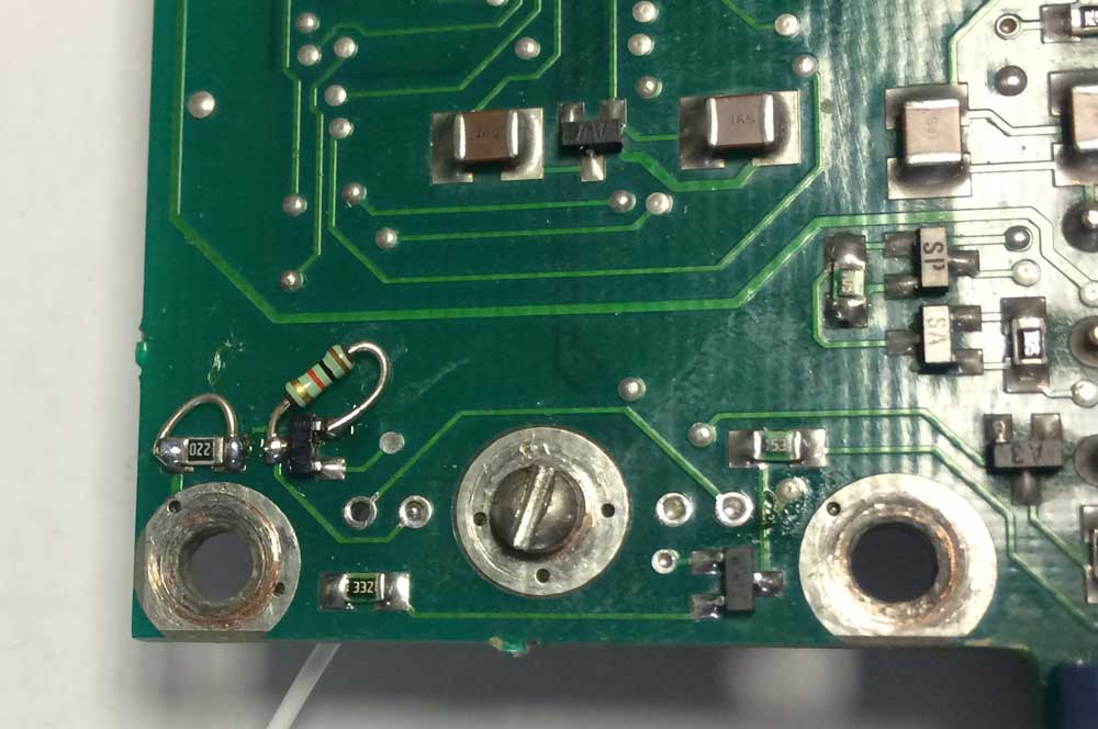
Oh, one more thing in the hardware, you have to remove the little gold case FET on the CPU card near pin 72 of the connector. This will allow the processor to run when the missing cards are out.
Once running, the displays blinks 6 6 6 five times and shuts off. After a lot of tracing, I’ve identified the display writing routine, error reporting, and the entire extensive POST routine.
Also discovered some funky backup battery scheme which I don’t understand at all quite yet.
Found the routing where the 6 6 6 is displayed and bypassed the call to that subroutine. Now the radio gives a 1 09 indication, or sometimes a 1 07 one. I bet this means some other CMOS signal is floating coming from the missing cards.
Probably going to wander around the software and try and figure out more stuff.