I’m done with the software for now. It was a big deal to get the radio programming mode to work right on my display but I’m through it.
I used my digital scope to trigger on I2C bus activity and captured the data stream the radio sent to the original display chips. I then scrolled through the data and clock and wrote down the bit values. I was able to determine that the way a digit was made to blink was to load a second page of segment on/off data and have the LCD control chips alternate between those two pages. The data would be identical except for the flashing digit which would be blank on one of those pages. Hence, it would flash.
The problem was that right after the second page data started being sent, the bus showed a conflict and the data wouldn’t get received or acknowledged. After finding nothing regarding this on the net, I considered all that could go wrong and realized the architecture of my code was wrong.
What I had been doing was to have nothing happen in the Arduino main loop and have all activity triggered when I2C data was received. This included the LCD chip device emulator and command decoder as well as processing all the data and writing to the new display. In normal operation, the data packet to the LCD chips was relatively infrequent, but the problem was that when put into programming mode, the radio sends two packets right next to each other, one to load each segment data page. Because my code remained in the receiveEvent interrupt service routine (ISR) so long it blocked reception of the second data packet.
What I did was restructure my code. I made the ISR as short as possible and I moved all processing and display code to the main program loop. Since I had everything stored in global variables this wasn’t terribly difficult. Now I have a continuously running loop which looks at stored raw display data and then processes and displays it and a completely separate asynchronous event which updates the data as it is received. I don’t need any lockout semaphores as it is only display data and the display is itself relatively slow responding.
Interestingly, this change fixed some odd and infrequent display bugs so now it is very solid. I did notice that the text messages (Tune, Pass, Good, etc.) were flickering so I added code to only write them once until the data changes and that resolved that issue.
What I do with the frequency digit data is to load to different locations in an array and if the radio is in program mode AND the digit data is different between the two areas (for each digit) I then set a bit indicating to the display routine to invert the digit. Here is what it ended up looking like: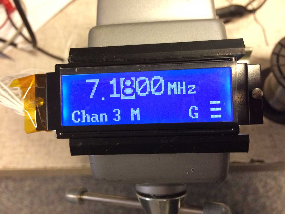
So now the radio frequency programming works like it should. All other messages and modes seem to work as well so now it’s time to move on towards wrapping up the last electrical and mechanical integration tasks.
I mentioned previously that the display brightness was very high, too high for most operation. The backlight LEDs are designed to be fed directly from 5 volts and there is a resistor on the LCD PCB. This is a transmissive display so you can’t just turn off the backlight as the display is nearly impossible to read. I experimented with adding series resistors and found that a 1k one gives a nice pleasant readable display in normal indoor light so there’s my choice. I will tie into the radio light switch so when that is turned on the display will go to full brightness which is necessary in bright outdoor sunlight conditions.
The LCD needs about -1.66 volts for contrast. I tried building a small diode charge pump running from the Arduino pin I set up for the LCD clock but there’s not enough drive so I’m going to use a charge pump chip which runs from the 5 volt supply directly. I have to order this as I don’t have any so will wait until I need some more parts from Digikey as I don’t want to pay $6 shipping for a 40 cent part. This will also give me a more regulated output.
Next I’m going to work on the mechanical mounting of the Arduino to the back of the LCD and getting that combo into the radio. I know the LCD itself fits beautifully but now I need to get that little Arduino in there nicely as well. I won’t be able to fully button it up until I get the charge pump IC but might jury-rig in a 7555 driven charge pump for the time being.
Once I have it all together I’ll write up the final installment of this and include the final wiring diagrams and mechanical photos.
The code can be found at: https://github.com/kb2vtl/Syncal_2000
P.S., I am still thinking about adding battery voltage. I also found out that the I2C addressing uses hardware on the Arduino Atmega328 processor so it will be extremely difficult to get it to monitor for mode and other data at different I2C bus addresses.
How about some video to show the operation of the original and new LCDs?
Excellent ! just an idea, if is posible to extend the signal bar (3 dash) to the top of the display?(add 4 more dashes) to bring more dynamics on the final graphics?
Not possible since the radio isn’t sending more info to the display. I’ll email you a version I just made which displays voltage, via an Arduino analog input pin.
Good to know that 😉