Category Archives: Radio

GRC-215 part 1

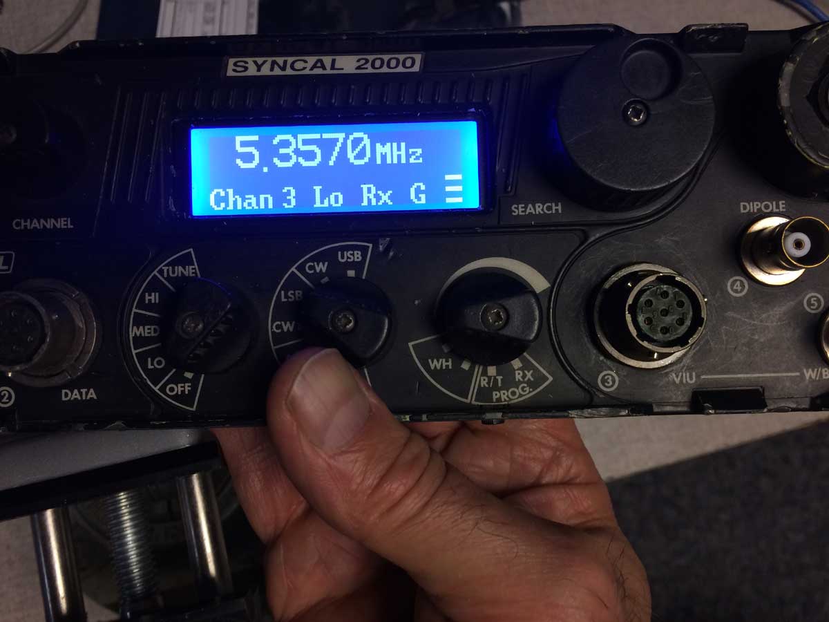
You’ve seen my requests for information on the GRC-215 man pack recently.

The GRC-215 is an unusual set.  It seems like almost an afterthought that it was made into a portable set.  I’ve been interested but several have told me that it is built of potted modules and unrepairable so I’ve stayed away.

This turns out to not be true.

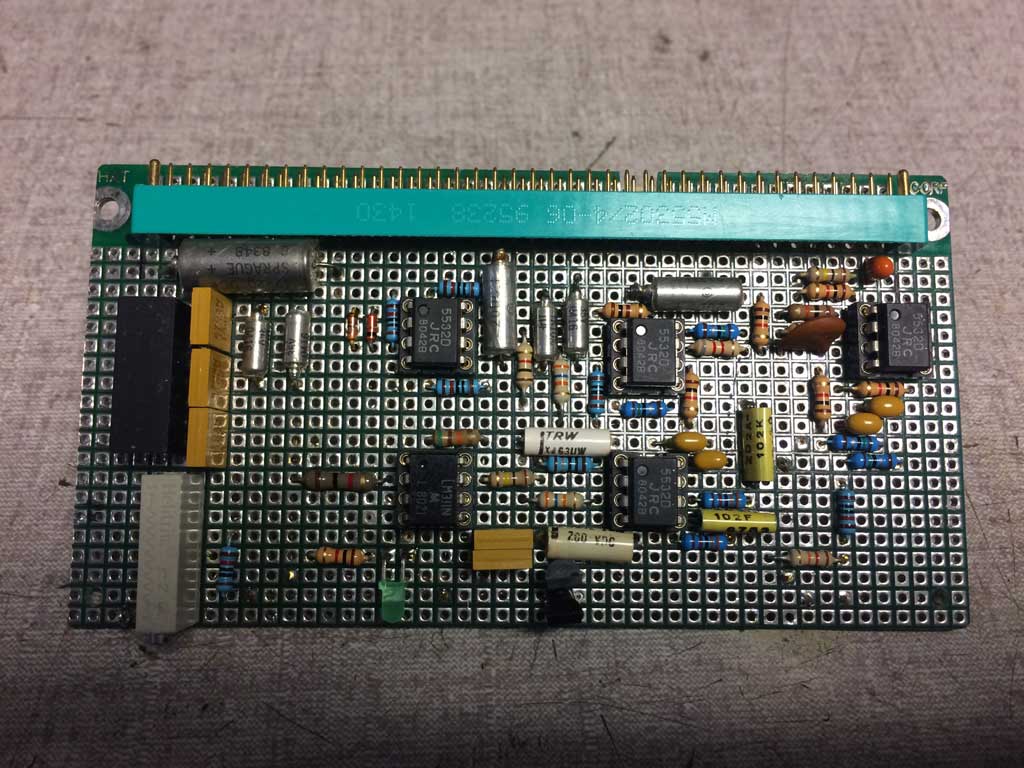
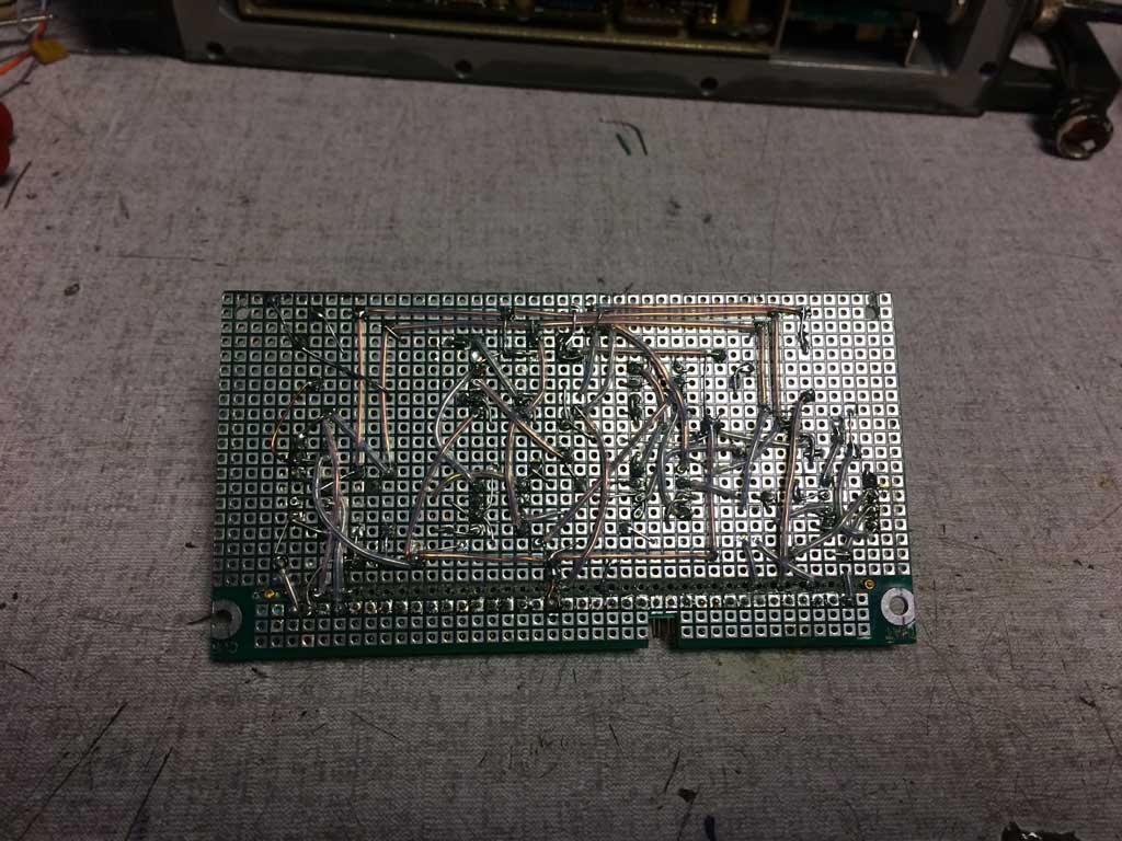
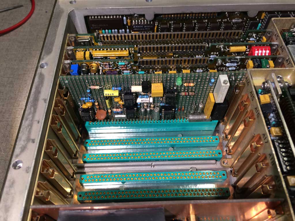
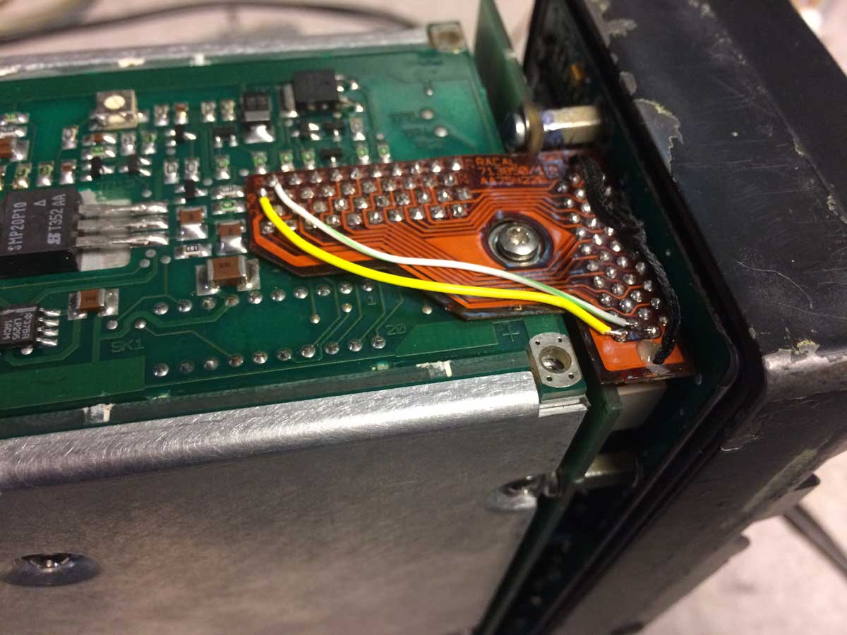
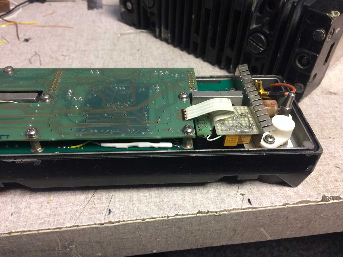
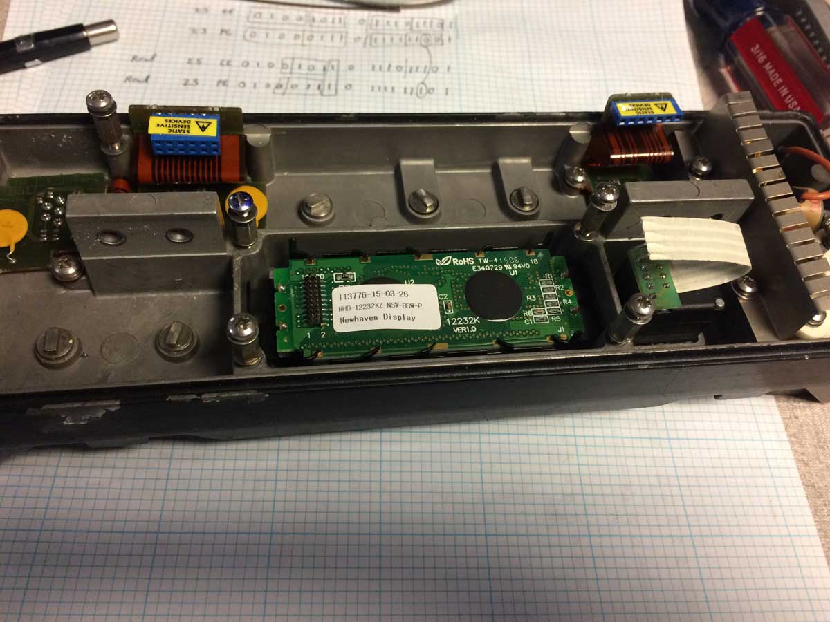
In any case, I had the opportunity to acquire one of these sets for a reasonable price, except it had a problem which seems to be an ATU tune failure.  Photos of the inside showed that the guts were not potted but rather conventional design so I went for it.

I found that detailed service information is EXTREMELY hard to find, most notably schematics.  A kind soul has sent me the module level manuals, which curiously have PCB component location diagrams and parts lists, but no schematics!  There is a general module wiring diagram with labelled signals included.

***

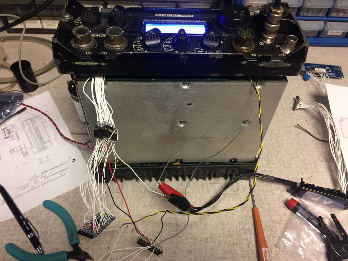
The fault is indeed that the ATU does not tune, but oddly enough, the tuner tries even when it’s not supposed to, when no whip is attached.

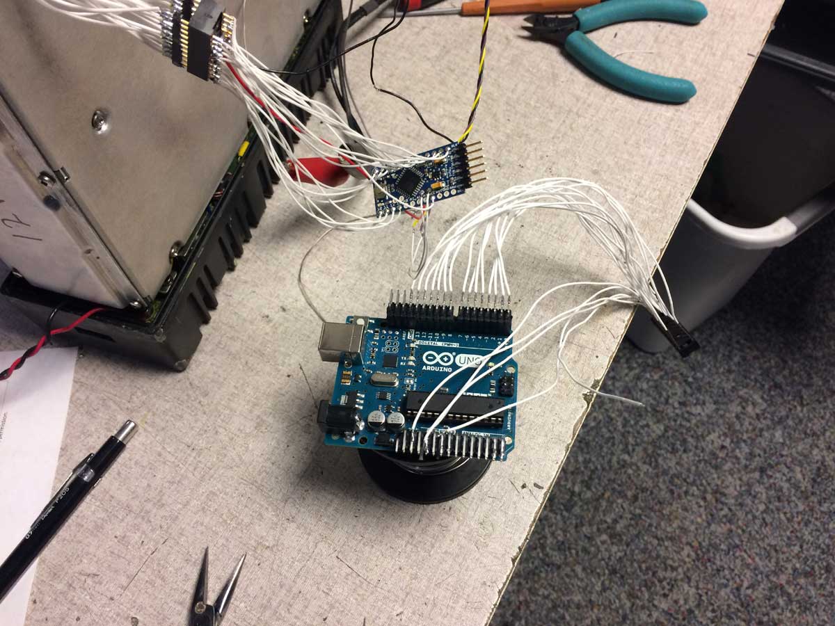
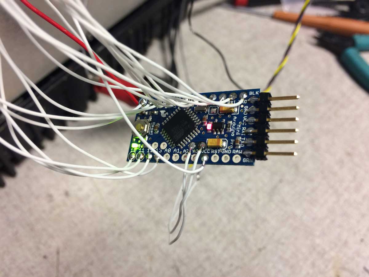
I made up a 25 pin D connector extension cable to operate the R/E with the ECCM control head detached.

After a little reading of the very basic qualitative circuit descriptions I understand that there is a “50 ohm” signal which comes from the ECCM unit to tell the switching logic to send the PA output to the BNC connector and disable the ATU.  As the ATU always seems to run, I took a look at this signal and it indeed is always indicating to (falsely) use the tuner.  That’s a problem.

But where does this signal come from?  There is a switch in the whip connection which activates when a whip is attached, but all that seems to do is make the RF path to the whip.  There is a capacitor to a coax back to switching relays but no sense connection.  How does the ECCM know whether a whip is connected or not?  There is no explanation of how this works that I can find in the manuals, and it definitely isn’t working.

Well, what about if I just attach a whip?  Tried that, same ATU fail problem.

Here’s a weirdness:  not knowing how the radio works I placed a wattmeter and dummy load on the BNC connection.  During the tune cycle the power goes up to about a watt before ending in failure. Why would the tuner affect the 50 ohm output?  And what’s with the 1 watt?

I am suspecting a PA problem now.  In low power mode there should be 5 watts out.  Was the PA damaged by a problem in the antenna switching leading to running into an open?  That’s pure conjecture. But very low tune power could definitely lead to faults being registered and tune failure.

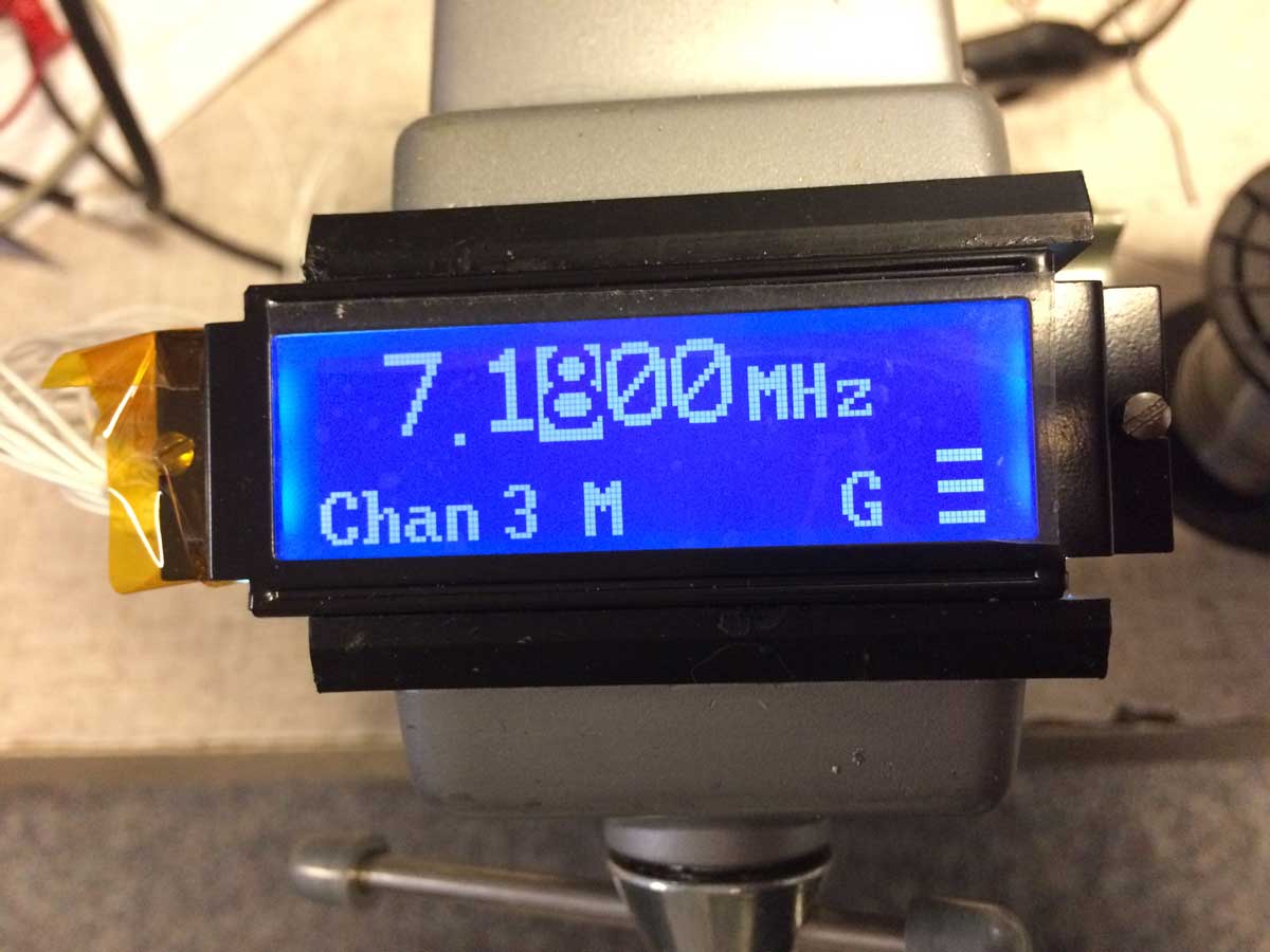
So I decided to see what happened if I changed that 50 ohm signal. Since I have the ECCM on an extender cable I disconnected that signal and grounded it.  First I did it the wrong way and nothing changed (duh) but I realized my stupid mistake and grounded the correct side and sure enouth the tuner doesn’t run and I get the full 1 watt on the BNC right away.

So the handset is specially wired and called a H-356.  Modifying a H-250 is tough as there aren’t enough wires in the cord but I found it is possible to modify a H-350 handset as used in those digital field phones.

Looking on a scope there is a good SSB modulation, but only 1 watt. Going to high power gets to 5 watts.  Should be 25.

So, one of the following:
1)  PA problem
2)  drive problem
3)  control problem
4)  harmonic filter problem

I tried on a bunch of different frequencies and they all behave the same so I’m thinking it’s not #4 but I will still check.

Now I need to open the unit up enough to get some test points temporarily brought out when I put it together and look at maybe the ALC first, then undo and extend the little coax in and out connectors to the PA itself and measure those.  That will be next!

KY-67 Adventure

I have some catching up to do in terms of the full story here so this time I’ll start with the bottom line, a fully working radio.

The KY-67 was designed as a super heavy duty 30-76 MHz FM military pack set with built in encryption.  Since encryption devices are not allowed to be surplussed out, the crypto boards have been removed from all of these radios which made it out.  Unfortunately, for a number of reasons hardware and software, the radio will not operate as a regular radio without those cards.

I read out the microprocessor code and after disassembly was able to patch the code to allow it to run without the crypto cards present.  Removal of a FET allowed the processor to run with missing hardware.

The last part was that both receive and transmit audio go through the missing cards.  To solve that I had to build equivalent circuitry.  Here is a picture of the top of the card I made:

Here is the bottom:

And here it is in the radio:

With this done (and a few jumpers on the backplane) the radio operates as it should.  Volume, squelch and squelch disable all work as intended.  Those functions and both transmit and receive audio amps and filtering are on the new card.

Oh, and one more fun thing:  another very smart engineer joined me later on in this project (very pleased to meet an engineer of that caliber!) and located in the code where it could be patched to extend the low frequency limit from 30 to 28 MHz.  So now the radio will do FM on 10 meters as well as 6!

Getting a KY-67 to run

I guess time to post here rather than just on the Yahoo milpack group.  This way it’s easier to find all the updates in one spot and in order.

The KY-67 is a very rugged VHF backpack transceiver covering the usual 30-88 MHz and made in the eighties.  My impression was that it was made for an amphibious vehicle which experienced program delays so by the time the program went into production the radio’s technology and features were dated and not many were produced.

The unique part for the time was that the radio had integral digital encryption.  Of course what this means is that for all radios which were surplussed the encryption boards had to be removed so every one of these anyone outside the military has seen is missing all those cards.  While I commend the surplus disposition people for not just grinding the radio up to scrap, the removal of those boards renders the radio inoperational.  Completely dead.  Some have tried, but no word of anyone ever succeeding.  Of course, the funny part is that I will likely only use this radio several times a year, and probably all on 51.0 MHz.  But it looks really cool and rugged, like you could run over it with a truck.  So I’m going to try and get it to run.

A kind soul offered me one with mounting base, unused, for the cost of shipping.  Let the games begin, it against me.

Next post I’ll add some photos.

Here’s a summary of my progress to date:

Two battery connectors for two 2590 type batteries.  One runs the encryption boards, the other the radio itself.

The CPU board operates the front panel display.  I was worried it might be controlled by the missing cards.  CPU is a NSC800, an extended temperature range Z80,  Firmware was on a socketed (yay!) 27C256.  Hmm, only 64k instructions at most, doable..

Read it out, ran some Z80 disassembler I found on the web, got this:

https://github.com/kb2vtl/KY-67

Look at the .asm file, that’s the one I’m annotating as I go.

Oh, one more thing in the hardware, you have to remove the little gold case FET on the CPU card near pin 72 of the connector.  This will allow the processor to run when the missing cards are out.

Once running, the displays blinks 6 6 6 five times and shuts off.  After a lot of tracing, I’ve identified the display writing routine, error reporting, and the entire extensive POST routine.

Also discovered some funky backup battery scheme which I don’t understand at all quite yet.

Found the routing where the 6 6 6 is displayed and bypassed the call to that subroutine.  Now the radio gives a 1 09 indication, or sometimes a 1 07 one.  I bet this means some other CMOS signal is floating coming from the missing cards.

Probably going to wander around the software and try and figure out more stuff.

Syncal 2000 display project, part 16 final

I wrapped up the radio for the time being.  It’s not internally 100% the way I’d like it but I need some time to work with it before I consider the firmware truly final.

A few notes:
1)  I traced out the radio LCD backlight wiring.  There are four LEDs in series with the high side connected to 10 volts and the low going through a transistor and resistor.  I had previously found that 1k in series was nice for general LCD lighting and full 5 volts for high brightness.  I tied the new display positive backlight to +5 and the negative to the collector of that transistor.  I put a 1k resistor across the transistor and shorted out the 220 ohm resistor.  Here is what that mod looks like:

Yes, that’s a really tiny resistor I used!

2) The flex cable to the front processor board is not very robust.  Earlier I lost the ability to turn the radio on and found that the pin 40 to pin 40 connection was lost in the cable.  Now the 3 bars started going intermittent and I traced it to the loss of connection in pin 39.  Here is my fix:

About the only choice seeing as the part is unobtainium.  But it works great.

3)  The new LCD display annoyingly requires a negative ~1.66 volts for bias to work.  More annoyingly there is no negative supply I could find in the radio so I had to make a small 555 based charge pump.  I would prefer to use a tiny SO-8 part to do this, one meant for the purpose, but that will have to wait until I have enough to order from Digikey to have a reasonable size order.  In the meanwhile I stuffed it here:

Left of that are three precision resistors which make the voltage divider for the voltage display I added.  When I go back in I will tack glue three SM resistors on the other side to eliminate this eyesore.  Here is where the sense wire ends up connecting to the CPU board pin 39:

I didn’t take a photo of it but have the 6 wires from the Arduino going to a tiny connector which is between the boards.  I can connect my code development computer to it if I want to update the code without having to disassemble the whole thing.

I took a video but it is too large for this site so I placed it on my site at the following address:

http://petergottlieb.com/images/syncal.mov

Note that when the display goes to the bright setting the iPhone camera can’t handle it and washes out.  It’s pretty bright, gotta love these new high efficiency LEDs!

Now I play in the field!


Syncal 2000 display project, part 15

I’m done with the software for now.  It was a big deal to get the radio programming mode to work right on my display but I’m through it.

I used my digital scope to trigger on I2C bus activity and captured the data stream the radio sent to the original display chips.  I then scrolled through the data and clock and wrote down the bit values.  I was able to determine that the way a digit was made to blink was to load a second page of segment on/off data and have the LCD control chips alternate between those two pages.  The data would be identical except for the flashing digit which would be blank on one of those pages.  Hence, it would flash.

The problem was that right after the second page data started being sent, the bus showed a conflict and the data wouldn’t get received or acknowledged.  After finding nothing regarding this on the net, I considered all that could go wrong and realized the architecture of my code was wrong.

What I had been doing was to have nothing happen in the Arduino main loop and have all activity triggered when I2C data was received.  This included the LCD chip device emulator and command decoder as well as processing all the data and writing to the new display.  In normal operation, the data packet to the LCD chips was relatively infrequent, but the problem was that when put into programming mode, the radio sends two packets right next to each other, one to load each segment data page.  Because my code remained in the receiveEvent interrupt service routine (ISR) so long it blocked reception of the second data packet.

What I did was restructure my code.  I made the ISR as short as possible and I moved all processing and display code to the main program loop.  Since I had everything stored in global variables this wasn’t terribly difficult.  Now I have a continuously running loop which looks at stored raw display data and then processes and displays it and a completely separate asynchronous event which updates the data as it is received.  I don’t need any lockout semaphores as it is only display data and the display is itself relatively slow responding.

Interestingly, this change fixed some odd and infrequent display bugs so now it is very solid.  I did notice that the text messages (Tune, Pass, Good, etc.) were flickering so I added code to only write them once until the data changes and that resolved that issue.

What I do with the frequency digit data is to load to different locations in an array and if the radio is in program mode AND the digit data is different between the two areas (for each digit) I then set a bit indicating to the display routine to invert the digit.  Here is what it ended up looking like:

So now the radio frequency programming works like it should.  All other messages and modes seem to work as well so now it’s time to move on towards wrapping up the last electrical and mechanical integration tasks.

I mentioned previously that the display brightness was very high, too high for most operation.  The backlight LEDs are designed to be fed directly from 5 volts and there is a resistor on the LCD PCB.  This is a transmissive display so you can’t just turn off the backlight as the display is nearly impossible to read.  I experimented with adding series resistors and found that a 1k one gives a nice pleasant readable display in normal indoor light so there’s my choice.  I will tie into the radio light switch so when that is turned on the display will go to full brightness which is necessary in bright outdoor sunlight conditions.

The LCD needs about -1.66 volts for contrast.  I tried building a small diode charge pump running from the Arduino pin I set up for the LCD clock but there’s not enough drive so I’m going to use a charge pump chip which runs from the 5 volt supply directly.  I have to order this as I don’t have any so will wait until I need some more parts from Digikey as I don’t want to pay $6 shipping for a 40 cent part.  This will also give me a more regulated output.

Next I’m going to work on the mechanical mounting of the Arduino to the back of the LCD and getting that combo into the radio.  I know the LCD itself fits beautifully but now I need to get that little Arduino in there nicely as well.  I won’t be able to fully button it up until I get the charge pump IC but might jury-rig in a 7555 driven charge pump for the time being.

Once I have it all together I’ll write up the final installment of this and include the final wiring diagrams and mechanical photos.

The code can be found at:  https://github.com/kb2vtl/Syncal_2000

P.S., I am still thinking about adding battery voltage.  I also found out that the I2C addressing uses hardware on the Arduino Atmega328 processor so it will be extremely difficult to get it to monitor for mode and other data at different I2C bus addresses.


Syncal 2000 display project, part 14

Mystery solved.

One of the oddities of the Racal transceiver is how the front panel switches work.  There is a PCB right behind the front panel and it has a number of PCB mounted selector switches which take a flat blade to turn them.  The panel itself has shafts which go to the knobs and they have this flat blade which mates with the switches.  This allows for the shafts to be environmentally sealed and not require it of each individual switch.  Not a bad idea, but there is a hitch in that it is possible to have the tab 180 degrees off and then the switch will use positions it wasn’t intended to and this can cause mal-operation.

When I put the panel back together I thought this was what was happening with the Prog switch.  When I rotated it to the program position, the display went dark, voltages messed up, all sorts of grief.   So I disassembled and discovered, based on marks I had made, that it wasn’t rotated 180.  Uh-oh, something’s wrong with the radio.

Well, I don’t have the schematics, they seem impossible to get, so I’m kind of on my own so I started investigating further.  The radio also had other faults.  Receive had a loud pulsating noise and tuning, even into a dummy load, always resulted in a “Fail” indication.  Looked serious.

The first thing I did was to look at the 5 volts going to the display.  Well, it went down to 4.3 when I went into program mode.  Hmmm, how can that be?  Did I have a pinched wire?  So I removed the display and put it on the bench, no change.  Then I hooked the Arduino and display to a separate power supply.  That will fix it, right?  Wrong!  But how can that possibly be?  Well, it turns out that what I thought was the ground (Vss) connection wasn’t!  It was some sort of signal!  It was just low most of the time.  Connecting to actual chassis ground (for now) solved that problem and resolved ALL of the associated problems.  Now I can get into program mode.

The first thing I did was to hook the scope to the I2C bus.  I wanted to see if the CPU was “manually” toggling the blinking LCD segments.  It’s not, there’s no I2C bus activity during blinking.  This means the blinking is done by the LCD chips.  Oh, that’s a pain.  Why?  Because the way that works is to load another entire page of segment bits and set the LCD chip to rapidly toggle between pages.  Why is this a pain?  because that means I now have to look for the CPU storing another page of segment data and determine which ones are different and use that to identify which segment is the blinking one.  This will take some work, although I’m sure I have enough code space as so far I’m only using 28% of what’s available.

When I get into program mode some of the display data is wrong, such as channel number, so I think I have a problem in my LCD chip emulation code which I’ll have to investigate.  Well, at least the radio can be programmed now and I get a “Good” on tune.

More tomorrow.


Syncal 2000 display project, part 13

Uno to Pro Mini  transition

Up until this point I have been doing all my development and testing using the Arduino Uno, even though my plan all along was to use the Arduino Pro Mini.  Both use the same processor, run on 5 volts, and have a 16 MHz clock.  The difference is that the Pro Mini uses a surface mount part instead of through hole and eliminates the on-board USB interface.  The Mini Pro is a very tiny board and is theoretically code compatible with the larger Uno.  Nevertheless, the build definitions file used in the compiler is different and I decided to switch over to the Mini Pro for further development to make sure there weren’t any “gotchas.”  Here are a few photos showing the size comparison.

The 6 pin header on the Mini Pro (on top) has 0.1 inch spacing.  The wire is 28 AWG teflon stranded for the Mini, 26 AWG for the Uno below it.  Here is a close-up of the Mini.  The header, by the way, is for connection to the computer for programming via a FTDI USB interface.

Here is the computer interface:

That’s one of those really tiny USB mini connectors.  On the back side is a 6 pin socket to plug into the Mini.

Here is the Mini connected to the radio:

I’m using a 20 pin DIP socket as my connector so I can bring the Mini to my desktop computer to load code to it.  That socket is nearly as large as the Mini board itself.

Initially I had build and communications errors between the computer and Mini but figured out what I needed to change in the settings, which wasn’t all that difficult and pretty obvious when I went in.  I needed to change the port from COM7 to COM8 for the new device and also needed to change the target board to Mini Pro from Uno.  Then it all worked and code loaded.  Plugging it into the radio showed that it worked perfectly so it seems the two are indeed pretty compatible.

One very interesting suggestion I got was to display actual battery voltage on the screen.  I thought the on-chip A/D was 8 bits but I was wrong, it’s 10 bits, so that would give a pretty solid XX.X volt display.  If I set the full scale to 15 volts that means each LSB is 15 mV so I could almost go to XX.XX if I really wanted.  I’m not sure I can nicely fit these digits onto the screen, although I’m playing with layouts using a 5×7 basic font for this voltage, reducing the size of the existing battery bars (which are also used for transmit power indication), and moving some of the lower status row letters closer together.

Peter


Syncal 2000 display project, part 12 – question

So I’ve gotten further now with the display, trying to move various things around.  I’d like to get some feedback on the layout I have; the good, bad and ugly of it.  So here it is right now:

The leading zero on the frequency is blanked.  The space to the right of the frequency is for a left or right arrow, I haven’t coded that functionality yet.  The bottom line is what I call the status line and shows the selected channel (if channel 0, I just have “VFO”), then Lo Md or Hi power, then Rx when squelch is open, then a letter to remind me what segment of the band I’m in (none, G for General or X for Extra), then a 3 bar bargraph to indicate battery voltage in receive and transmit power in transmit.

I want thoughts on how I’ve laid it out.  There are still things that need to be done, for example the tune, good and fail messages (probably like the original display, in the frequency area for just a second or two).  Also programming.  On that the original display blinks the digit being programmed but I’m not sure how they do that as there are two different ways for the original LCD chips so I’ll have to investigate further.  I don’t really like that method and would rather just invert black/white for the digit being programmed.  I think that’s nicer.

So, should I swap the Rx and power indication?  Should it be RX instead of Rx?  I tried to get the contrast and exposure such that you could see the extent of the pixel area to show where I’m up against the edges.

I might need to do some mechanical work next as I managed to zeroize the radio (the switches do not have stops when disassembled).  I think at this junction it is safe to remove the existing LCD control chips.  Or maybe not, maybe the processor will fault out if it doesn’t get I2C bus acknowledgement in the first few seconds while the Arduino bootloader is running and my program isn’t.  It is too inconvenient to disable that while I am going through many program iterations.  Well at least I can work out how to get the display mounted into the front casting.  I refuse to use glue, maybe I will form a very thin piece of brass sheet which goes under the screws which hold the front PCB in place.  On each side it would go from the standoffs shown below to the side bracket on the LCD, where I’d use 2-56 hardware to attach the formed brackets to the LCD mounting ears.

So, comments and critiques are sought and welcome!  This is all going to be open sourced so I’d like to put out there the best I can.

Syncal 2000 display project, part 11

It is remarkable how much I forgot about C programming.  It is definitely a perishable skill.  Nevertheless, I’ve muddled through.  I won’t bore you with all the iterations it took me to get to this point, and I’m certainly not done, but I do finally have the graphics display at least displaying frequency.

Here is what it looks like in the front panel of the radio, although still wired in all over my bench:

The display with full voltage to the LED backlight is quite bright, very easily readable in bright conditions.  I plan on having it run at very very reduced brightness except when the LED backlight in the radio is called upon to be on in which case I’ll go to full brightness.

Next is getting the status info onto the lower part of the display.  I’ll have to experiment with the font to see what looks best.  I will have a line like:

Chan 5   Power M

Then in the upper right will be the left or right arrows for tuning, the lower right will be the battery/transmit power bar indicator,  and after the power indication I was thinking of a band segment indicator (X or G) as a reminder just for fun.  I’ll also get the other misc things in there somewhere like the RX indicator, but I’ll have to play to optimize the visual look of this.

For messages, they’ll use good fonts instead of partial 7 segment and for “pass” I’ll show BITE PASS in the freq area.  So, a lot more work, but I’m getting there and it looks pretty decent!

Syncal 2000 display project, part 10

I spent quite a number of hours playing with code trying to control the new graphics display.  A lot goes into getting it to run; there of course is the hardware layer, then there is the writing of the basic routines to read and write to the display, then the higher level layers of writing commands to set it up, to select pages of internal memory, and the read-modify-write routines.

My last update involved the hardware layer and I did have to make a change.  I had a lot of trouble getting the basic Arduino IDE to accept some of the more arcane timer and interrupt commands I found on the net and I ended up with weird error messages which I ended up deciding were something I didn’t want to deal with right now.  So instead I went with what I mentioned in my last post of using the standard PWM output which I could get to 1 kHz as my LCD clock.  I had to move a couple wires around but it ended up working.

I had Vanyamba’s code as a starting point but wow did the standard Arduino IDE choke on it.  Again, tons of error messages at compilation which I had no idea what to do with.  Since his structure of commands seemed reasonable, I turned his basic display class written in C++ into regular C and brought it in to my code base.  Since I am doing a very specific project I really simplified it down.  After getting everything to compile without errors, I gave the code a simple task of writing some data to the display and loaded it.

Nothing happened.  No display, nothing.  I tried changing the LCD bias, no difference.  So I went back to basics and tried the code with simple commands and looked at the Arduino pins to see if they were doing what I wanted.  I studied the LCD control chip timing diagrams and discovered there was a race condition and swapped a couple of Vanyamba’s write statements which control pins and after verifying it on the scope I hooked up the display and that did it!   I have a slightly different display than he used so that may have made the difference.  Here is what the display looks like:

All the display setup works and I initialized it by filling the memory with 0xAA characters which is a 10101010 pattern.  Alright!

I think I’m going to use a 12×16 font for the main frequency display and under it a smaller 8×8 font  for channel number, power setting, etc.  I loaded the fonts into my program and will next concentrate on the read-modify-write of LCD memory to display them where I want.  That’s for another night.