So I’ve gotten further now with the display, trying to move various things around. I’d like to get some feedback on the layout I have; the good, bad and ugly of it. So here it is right now:
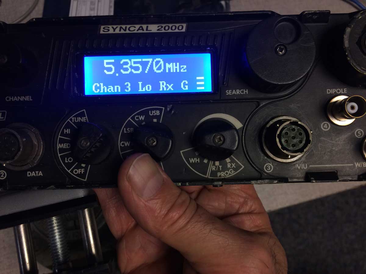
The leading zero on the frequency is blanked. The space to the right of the frequency is for a left or right arrow, I haven’t coded that functionality yet. The bottom line is what I call the status line and shows the selected channel (if channel 0, I just have “VFO”), then Lo Md or Hi power, then Rx when squelch is open, then a letter to remind me what segment of the band I’m in (none, G for General or X for Extra), then a 3 bar bargraph to indicate battery voltage in receive and transmit power in transmit.
I want thoughts on how I’ve laid it out. There are still things that need to be done, for example the tune, good and fail messages (probably like the original display, in the frequency area for just a second or two). Also programming. On that the original display blinks the digit being programmed but I’m not sure how they do that as there are two different ways for the original LCD chips so I’ll have to investigate further. I don’t really like that method and would rather just invert black/white for the digit being programmed. I think that’s nicer.
So, should I swap the Rx and power indication? Should it be RX instead of Rx? I tried to get the contrast and exposure such that you could see the extent of the pixel area to show where I’m up against the edges.
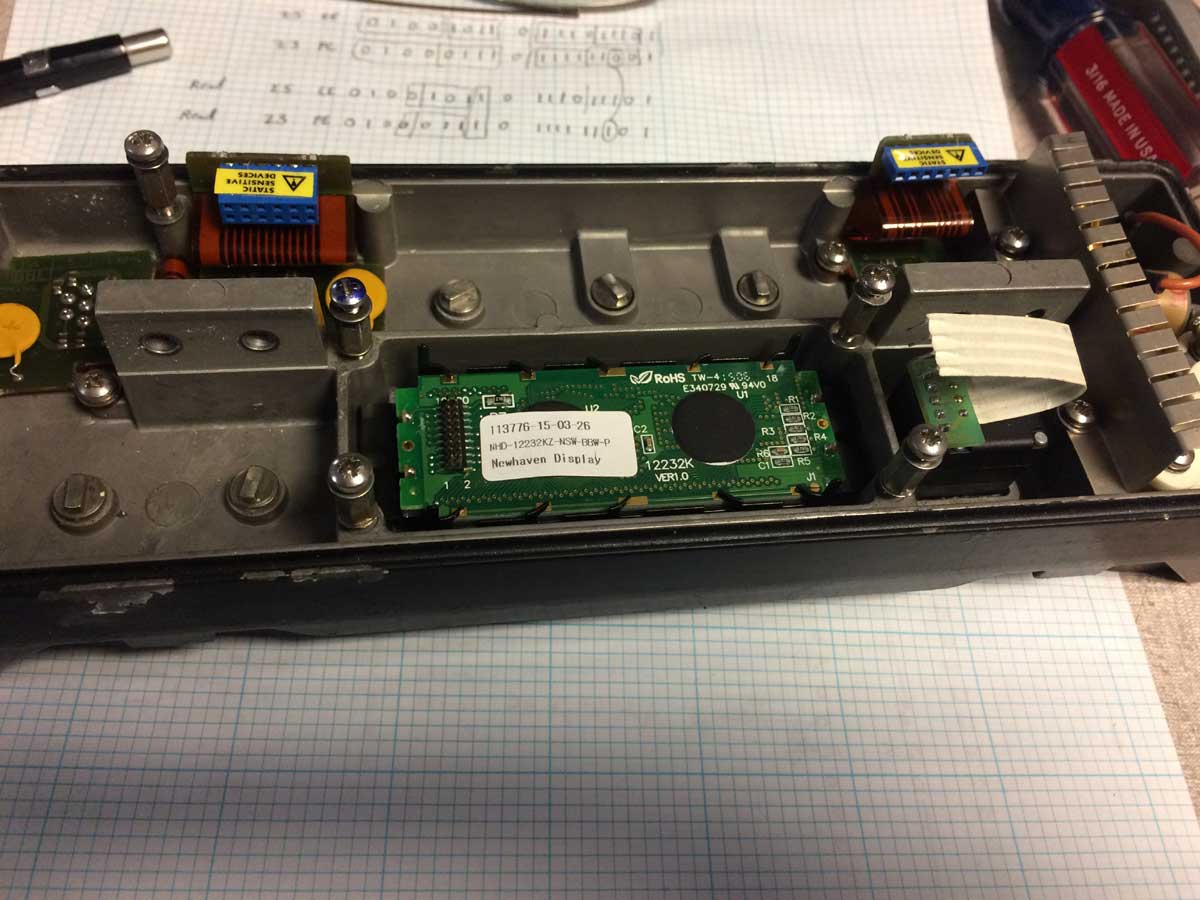
I might need to do some mechanical work next as I managed to zeroize the radio (the switches do not have stops when disassembled). I think at this junction it is safe to remove the existing LCD control chips. Or maybe not, maybe the processor will fault out if it doesn’t get I2C bus acknowledgement in the first few seconds while the Arduino bootloader is running and my program isn’t. It is too inconvenient to disable that while I am going through many program iterations. Well at least I can work out how to get the display mounted into the front casting. I refuse to use glue, maybe I will form a very thin piece of brass sheet which goes under the screws which hold the front PCB in place. On each side it would go from the standoffs shown below to the side bracket on the LCD, where I’d use 2-56 hardware to attach the formed brackets to the LCD mounting ears.
So, comments and critiques are sought and welcome! This is all going to be open sourced so I’d like to put out there the best I can.
Peter, I’m stunned that it is so good ‘as is’ I would say that if you can duplicate the standard display it would be fine…
Peter,
Very nice. Even my eyes can read the frequency. I’d like see the mode on the displayed.
Good suggestion, I would like to see the mode displayed as well. The existing display does not show it so it is a little tricky. I have seen different data go over the I2C data bus when the mode switch is changed so I’m pretty sure I know the address I need to look for when the radio is first turned on and the processor looks at all the different switches. The issue is that all devices on the bus have a different address and the library function for the Arduino is designed to work on one specific address, which is the LCD chip one. What I will need to do is modify the library function to remain acting like a responder to the LCD address but also monitor (without responding) the mode switch address. I do have this on my list but for after I get all the regular functionality up and running as I’ll need to verify I haven’t affected any of what I’ve already coded.