I spent quite a number of hours playing with code trying to control the new graphics display. A lot goes into getting it to run; there of course is the hardware layer, then there is the writing of the basic routines to read and write to the display, then the higher level layers of writing commands to set it up, to select pages of internal memory, and the read-modify-write routines.
My last update involved the hardware layer and I did have to make a change. I had a lot of trouble getting the basic Arduino IDE to accept some of the more arcane timer and interrupt commands I found on the net and I ended up with weird error messages which I ended up deciding were something I didn’t want to deal with right now. So instead I went with what I mentioned in my last post of using the standard PWM output which I could get to 1 kHz as my LCD clock. I had to move a couple wires around but it ended up working.
I had Vanyamba’s code as a starting point but wow did the standard Arduino IDE choke on it. Again, tons of error messages at compilation which I had no idea what to do with. Since his structure of commands seemed reasonable, I turned his basic display class written in C++ into regular C and brought it in to my code base. Since I am doing a very specific project I really simplified it down. After getting everything to compile without errors, I gave the code a simple task of writing some data to the display and loaded it.
Nothing happened. No display, nothing. I tried changing the LCD bias, no difference. So I went back to basics and tried the code with simple commands and looked at the Arduino pins to see if they were doing what I wanted. I studied the LCD control chip timing diagrams and discovered there was a race condition and swapped a couple of Vanyamba’s write statements which control pins and after verifying it on the scope I hooked up the display and that did it! I have a slightly different display than he used so that may have made the difference. Here is what the display looks like:
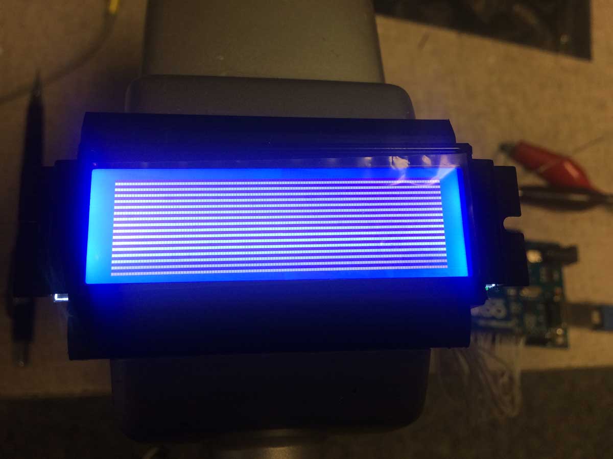
All the display setup works and I initialized it by filling the memory with 0xAA characters which is a 10101010 pattern. Alright!
I think I’m going to use a 12×16 font for the main frequency display and under it a smaller 8×8 font for channel number, power setting, etc. I loaded the fonts into my program and will next concentrate on the read-modify-write of LCD memory to display them where I want. That’s for another night.