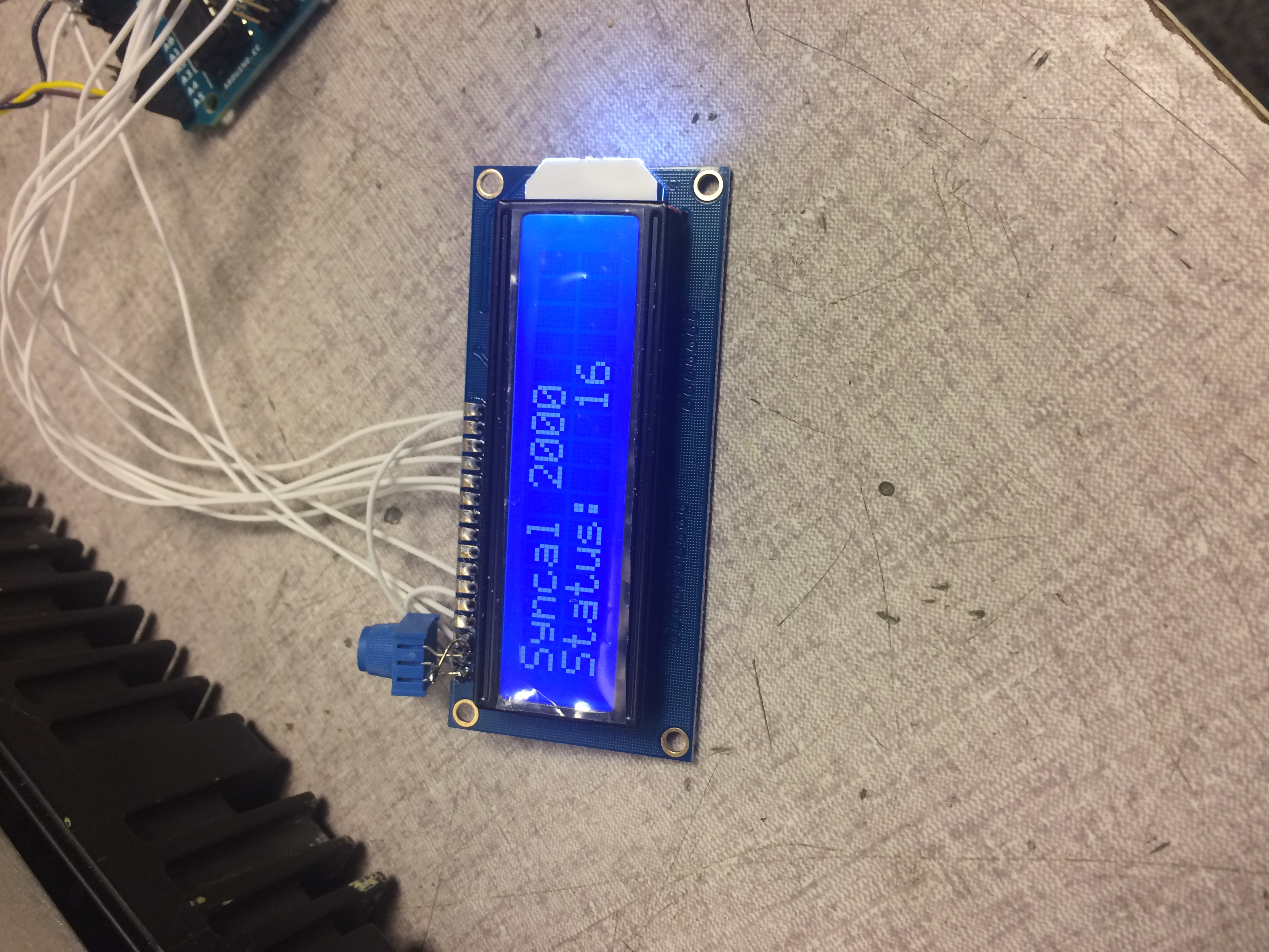
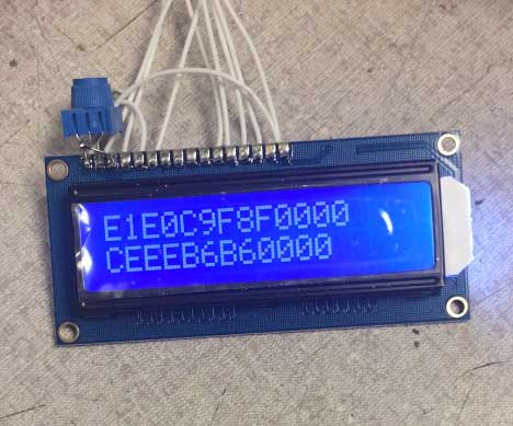
Some interesting data. I placed the old LCD against the zebra pads and realized that there was another item initially displayed, a “PASS” indication. I took a video of my Arduino LCD as the radio powered up and say this which happened just before that “PASS” indication:
Ok, so what does it mean?
E1 LCD chip device select 1
E0 LCD chip device select 0
C9 Mode set: static, normal, enabled, bias set
F8 RAM bank select: Bit 0 for both loading and display
F0 Blink mode: normal, off
Segment mapping is using the standard 7 segment A-G pattern:
00 10 MHz: blank
00 1 MHz: blank
CE 100 kHz: “P”
EE 10 kHz: “A”
B6 1 kHz: “S”
B6 100 Hz: “S”
00 Ch 10: blank
00 Ch 1: blank
Well, it does seem not all display writes have 16 bytes, and I’m not sure why some were missing from the first line, perhaps the Arduino is reading them faster than they are coming in, that doesn’t make any sense but in any case the above decoding makes perfect sense. I also captured a full data display in operation but will save decoding that for a later time, if it proves necessary or helpful.
So there it is! I’ve established:
1: The Arduino can read addr 57 I2C data from the Syncal 2000 radio control data bus
2: The status words being written to the LCD control chips make sense
3: My reverse engineering of the segments to loaded data make sense
Enough for tonight. Tomorrow we will go out but when I’m in later I will write some rudimentary code to interpret the data and write the radio frequency to the Arduino LCD display.
Things are moving quickly so I will also take final mechanical measurements and order the OLED display which best fits in the radio display available space. By the time it arrives I should be far enough along that I will have most original display elements written to variables and can start on creating a visually appealing OLED graphic display.
Peter