One of the steps I described earlier was to map the LCD segments to the LCD driver chip pins and then to the internal memory of those chips. This is because when I receive that data in my microprocessor I will have to be able to interpret it.
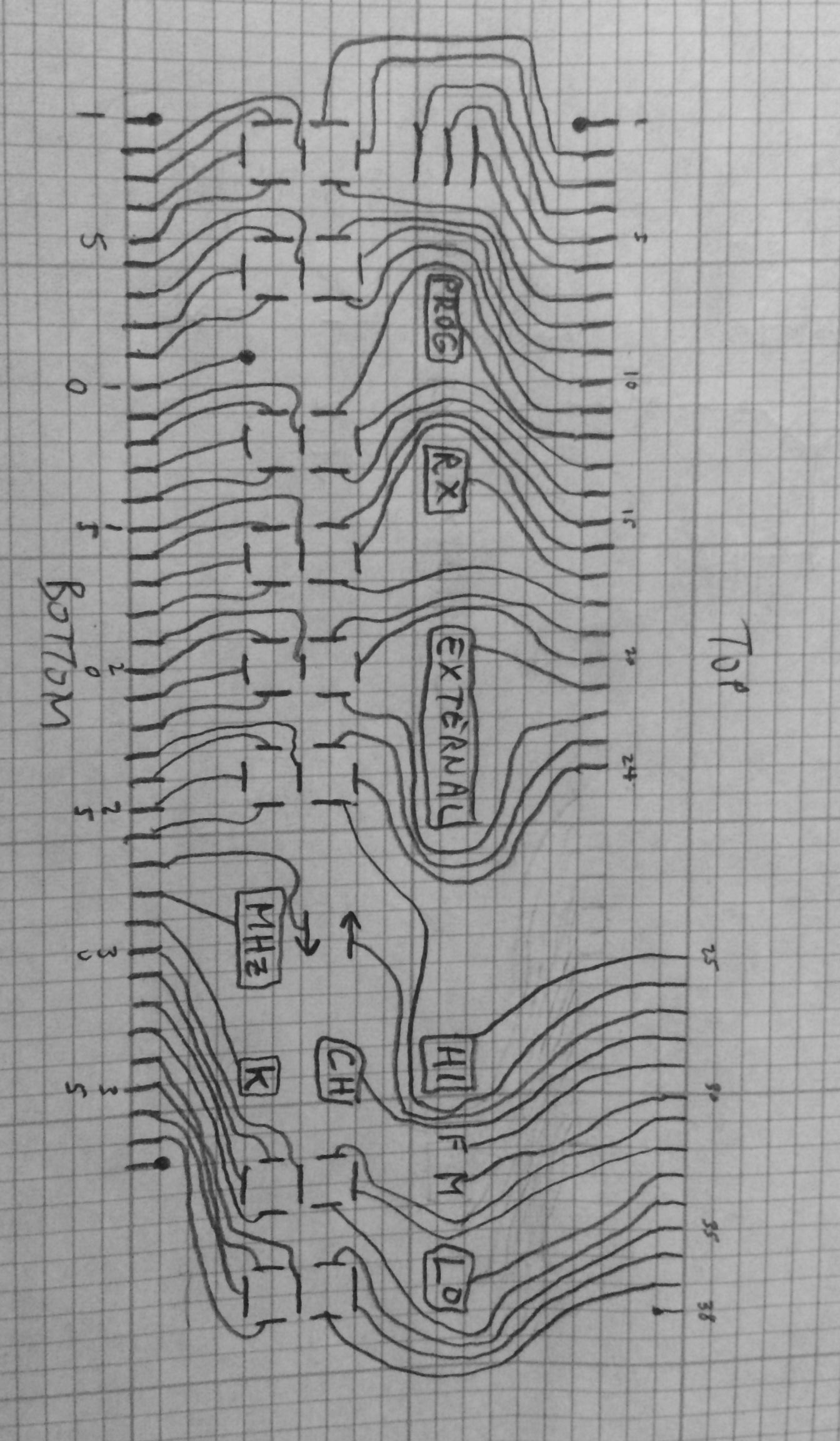
I first examined the LCD display itself and carefully followed each pin to a segment. I ended up with this sketch:
Then I used a special set of HP probes on the DMM in continuity mode. The probes are super tiny and have spring probe tips like used for PCB test probing. I followed each LCD pin back to the driver chips. That led to this:
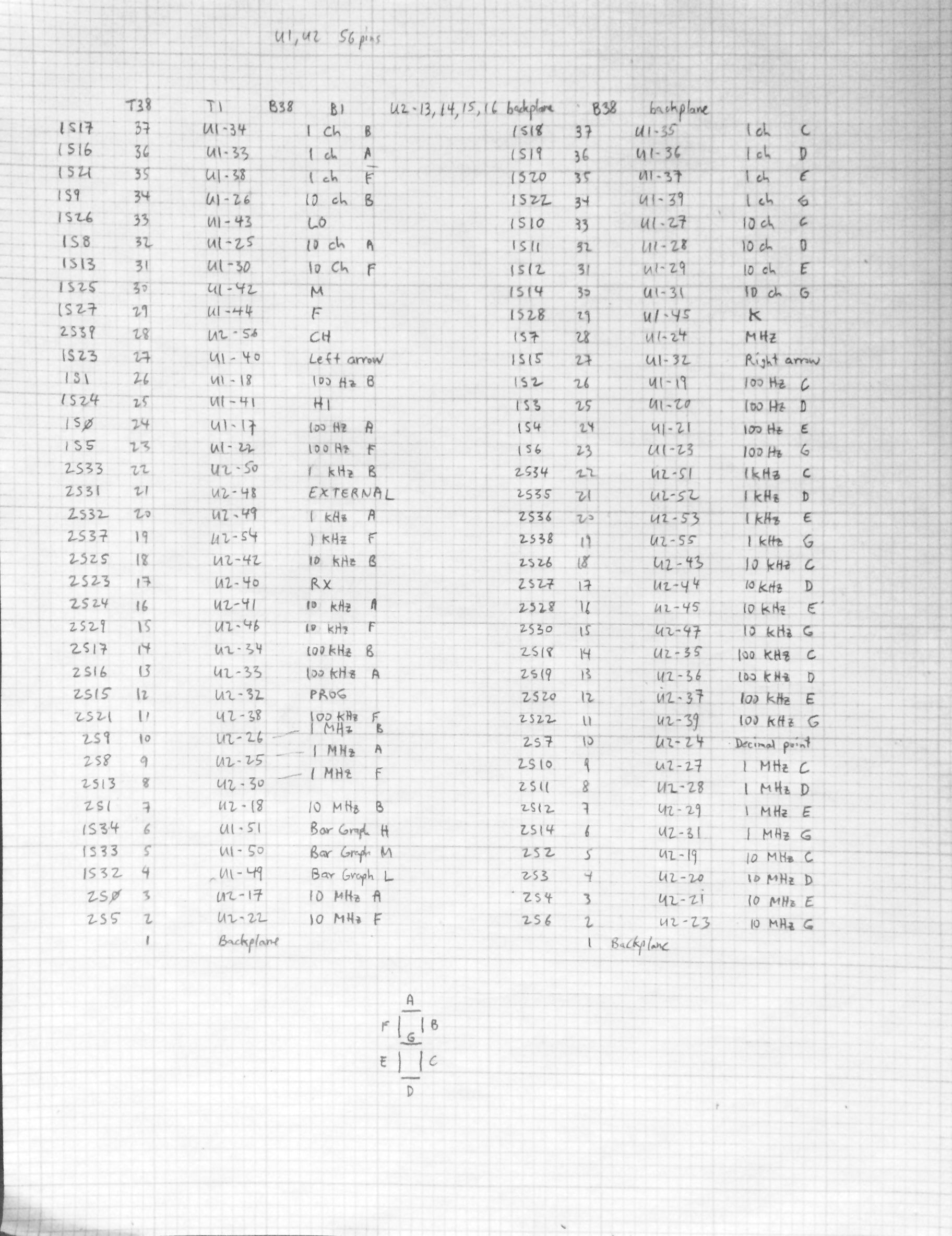
1S and 2S represent the two LCD driver chips. It turns out 2 is the low order and 1 is the high order addressed chip but that doesn’t matter. The S number is the segment output number of the chips. The 7 segment below has the standard segment labeling. Still looks confusing? Patience… Now I put the segment outputs in order and get:
LCD Driver 0 segment outputs
S0 10 MHz A
S1 10 MHz B
S2 10 MHz C
S3 10 MHz D
S4 10 MHz E
S5 10 MHz F
S6 10 MHz G
S7 Decimal point
S8 1 MHz A
S9 1 MHz B
S10 1 MHz C
S11 1 MHz D
S12 1 MHz E
S13 1 MHz F
S14 1 MHz G
S15 PROG
S16 100 kHz A
S17 100 kHz B
S18 100 kHz C
S19 100 kHz D
S20 100 kHz E
S21 100 kHz F
S22 100 kHz G
S23 RX
S24 10 kHz A
S25 10 kHz B
S26 10 kHz C
S27 10 kHz D
S28 10 kHz E
S29 10 kHz F
S30 10 kHz G
S31 EXTERNAL
S32 1 kHz A
S33 1 kHz B
S34 1 kHz C
S35 1 kHz D
S36 1 kHz E
S37 1 kHz F
S38 1 kHz G
S39 CH
LCD Driver 1 segment outputs
S0 100 Hz A
S1 100 Hz B
S2 100 Hz C
S3 100 Hz D
S4 100 Hz E
S5 100 Hz F
S6 100 Hz G
S7 MHz
S8 10 Channel A
S9 10 Channel B
S10 10 Channel C
S11 10 Channel D
S12 10 Channel E
S13 10 Channel F
S14 10 Channel G
S15 Right arrow
S16 1 Channel A
S17 1 Channel B
S18 1 Channel C
S19 1 Channel D
S20 1 Channel E
S21 1 Channel F
S22 1 Channel G
S23 Left arrow
S24 HI
S25 M
S26 LO
S27 F
S28 K
S29
S30
S31
S32 Bar graph L
S33 Bar graph M
S34 Bar graph H
S35
S36
S37
S38
S39
Now it makes sense, doesn’t it? So now I can decode the binary data sent to the LCD drivers.
I looked at the LCD driver chip data sheet (PCF8576) and see that there are both command and data words. Most of the command words have to do with LCD configuration and I can ignore them; I will have to pay attention to the cursor index set command but that is trivial.
To be continued…
One thought on “Syncal 2000 display project, part 3”
Comments are closed.