Syncal 2000 display project, part 14

Mystery solved.

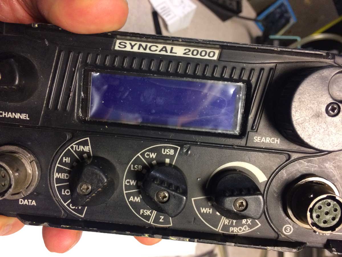
One of the oddities of the Racal transceiver is how the front panel switches work.  There is a PCB right behind the front panel and it has a number of PCB mounted selector switches which take a flat blade to turn them.  The panel itself has shafts which go to the knobs and they have this flat blade which mates with the switches.  This allows for the shafts to be environmentally sealed and not require it of each individual switch.  Not a bad idea, but there is a hitch in that it is possible to have the tab 180 degrees off and then the switch will use positions it wasn’t intended to and this can cause mal-operation.

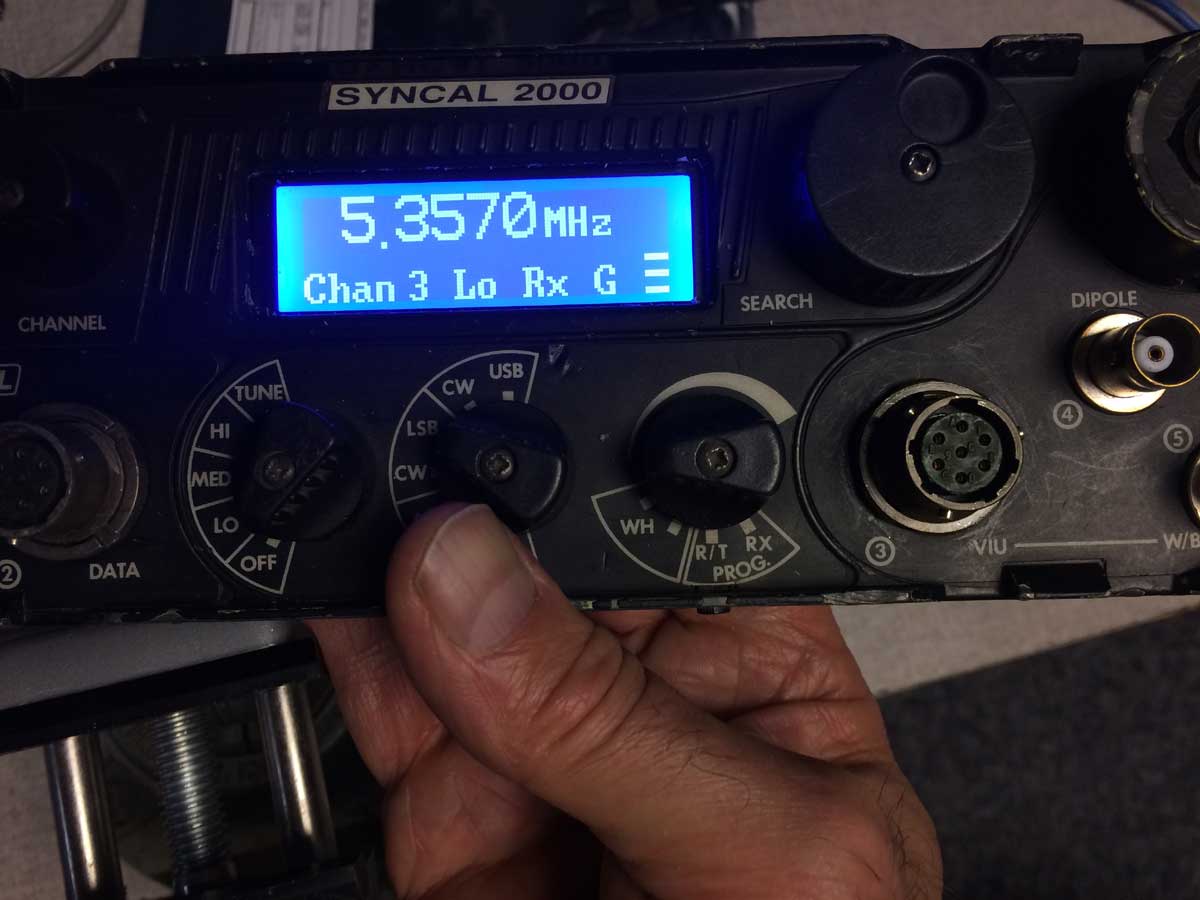
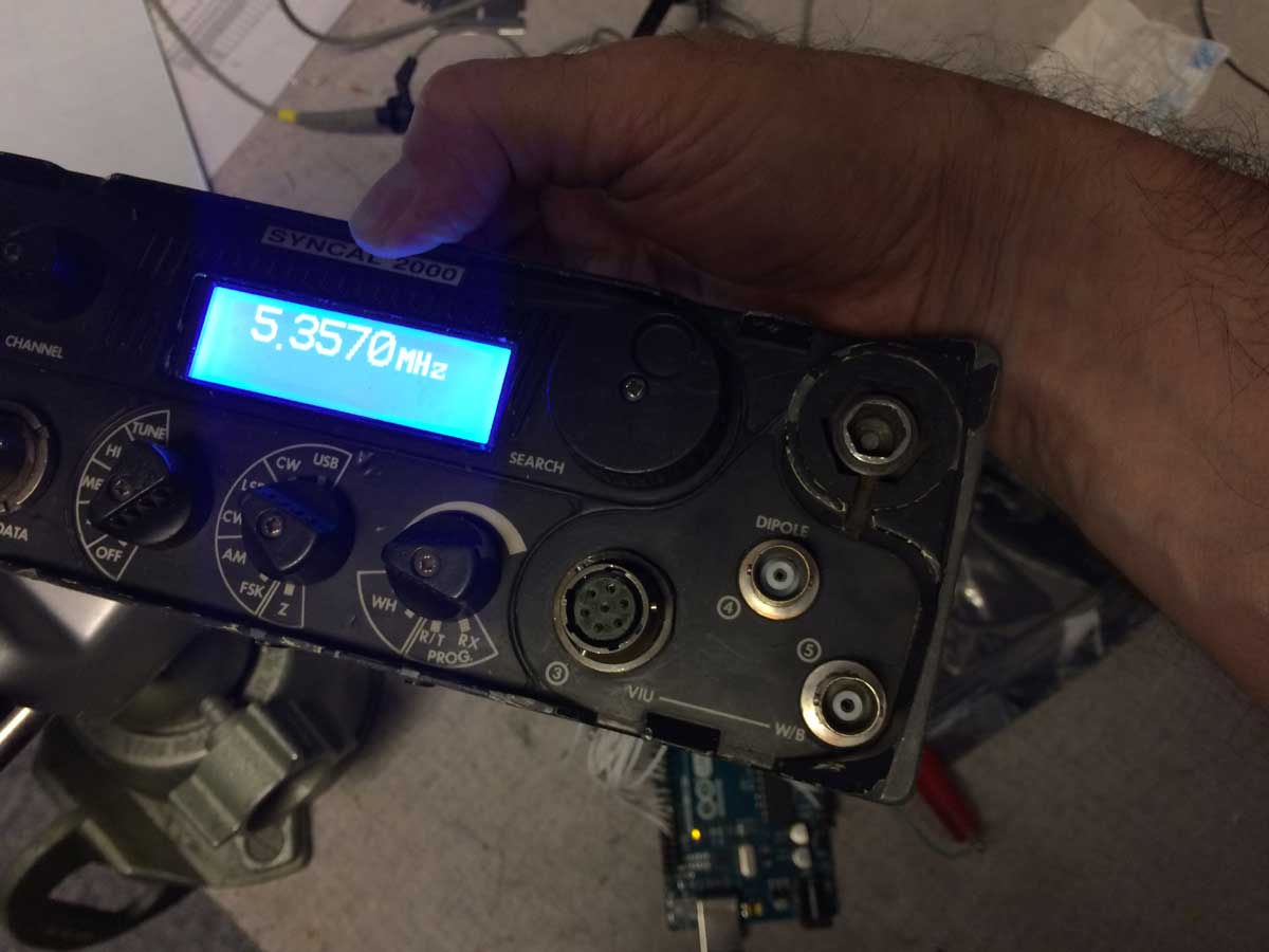
When I put the panel back together I thought this was what was happening with the Prog switch.  When I rotated it to the program position, the display went dark, voltages messed up, all sorts of grief.   So I disassembled and discovered, based on marks I had made, that it wasn’t rotated 180.  Uh-oh, something’s wrong with the radio.

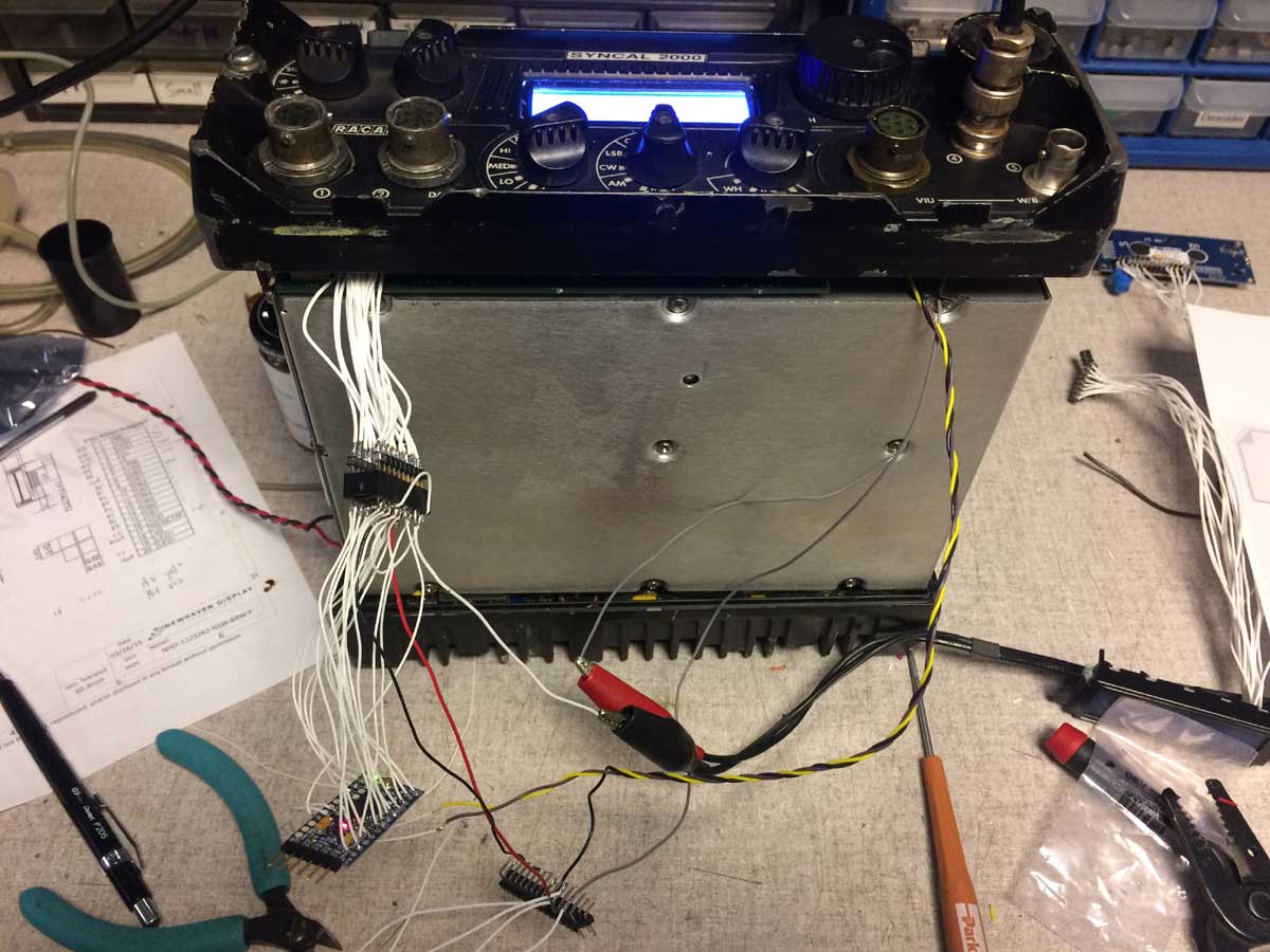
Well, I don’t have the schematics, they seem impossible to get, so I’m kind of on my own so I started investigating further.  The radio also had other faults.  Receive had a loud pulsating noise and tuning, even into a dummy load, always resulted in a “Fail” indication.  Looked serious.

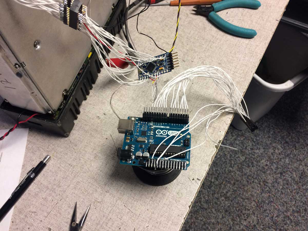
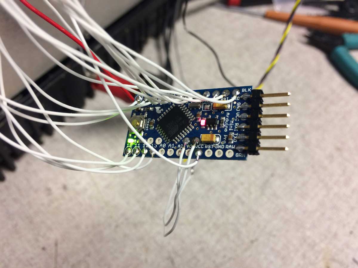
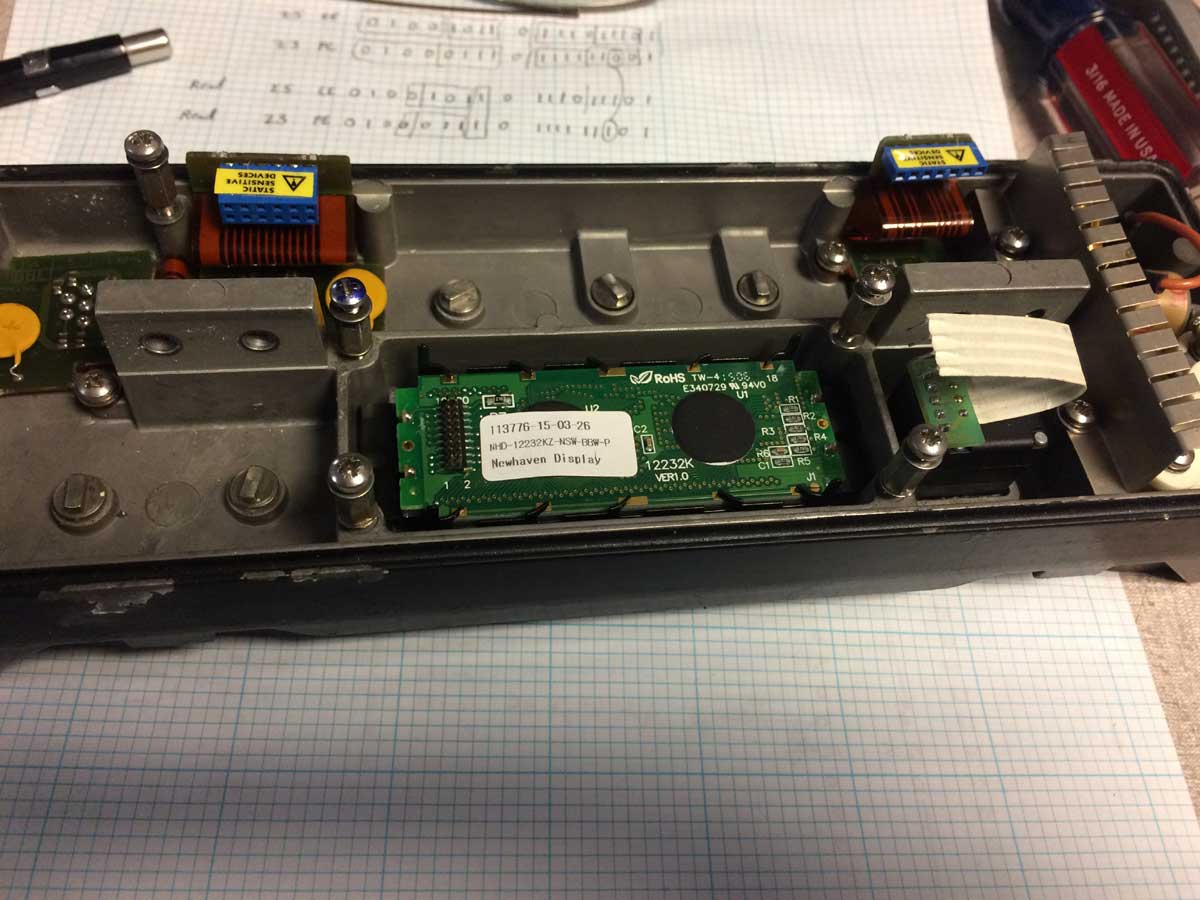
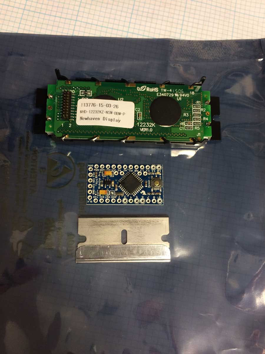
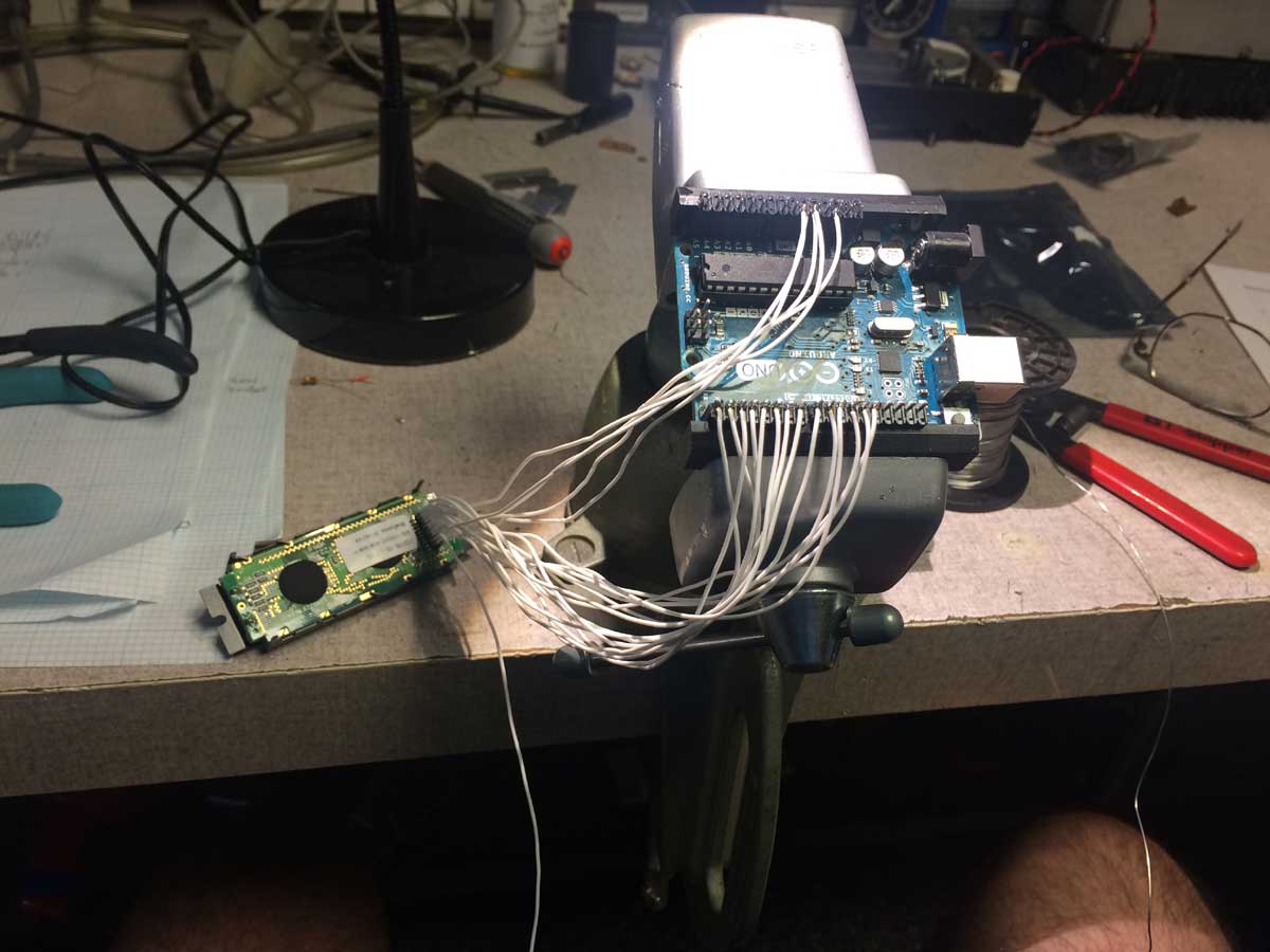
The first thing I did was to look at the 5 volts going to the display.  Well, it went down to 4.3 when I went into program mode.  Hmmm, how can that be?  Did I have a pinched wire?  So I removed the display and put it on the bench, no change.  Then I hooked the Arduino and display to a separate power supply.  That will fix it, right?  Wrong!  But how can that possibly be?  Well, it turns out that what I thought was the ground (Vss) connection wasn’t!  It was some sort of signal!  It was just low most of the time.  Connecting to actual chassis ground (for now) solved that problem and resolved ALL of the associated problems.  Now I can get into program mode.

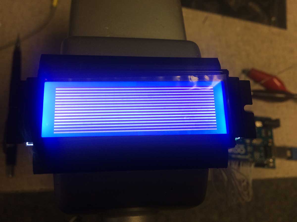
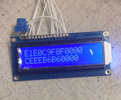
The first thing I did was to hook the scope to the I2C bus.  I wanted to see if the CPU was “manually” toggling the blinking LCD segments.  It’s not, there’s no I2C bus activity during blinking.  This means the blinking is done by the LCD chips.  Oh, that’s a pain.  Why?  Because the way that works is to load another entire page of segment bits and set the LCD chip to rapidly toggle between pages.  Why is this a pain?  because that means I now have to look for the CPU storing another page of segment data and determine which ones are different and use that to identify which segment is the blinking one.  This will take some work, although I’m sure I have enough code space as so far I’m only using 28% of what’s available.

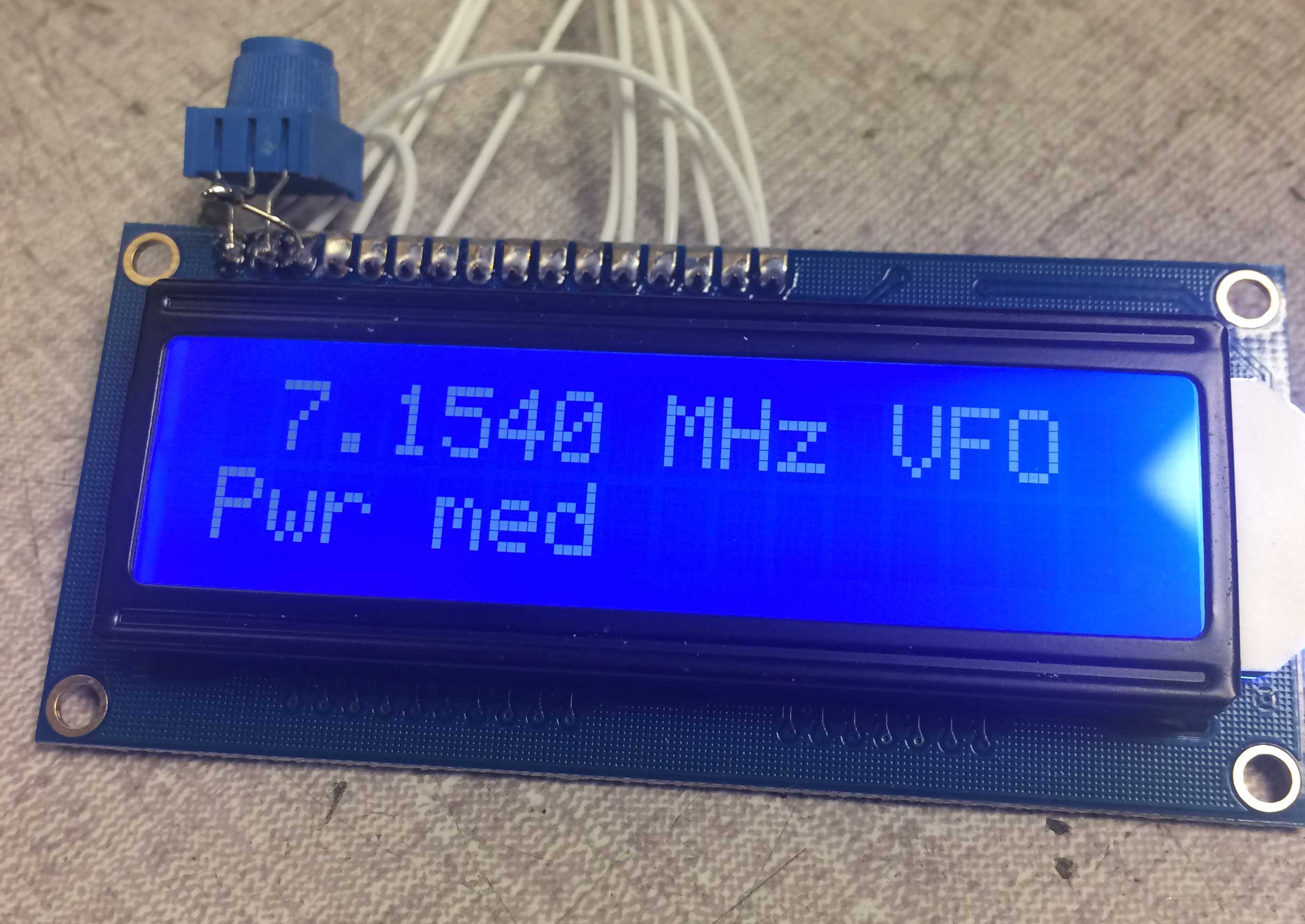
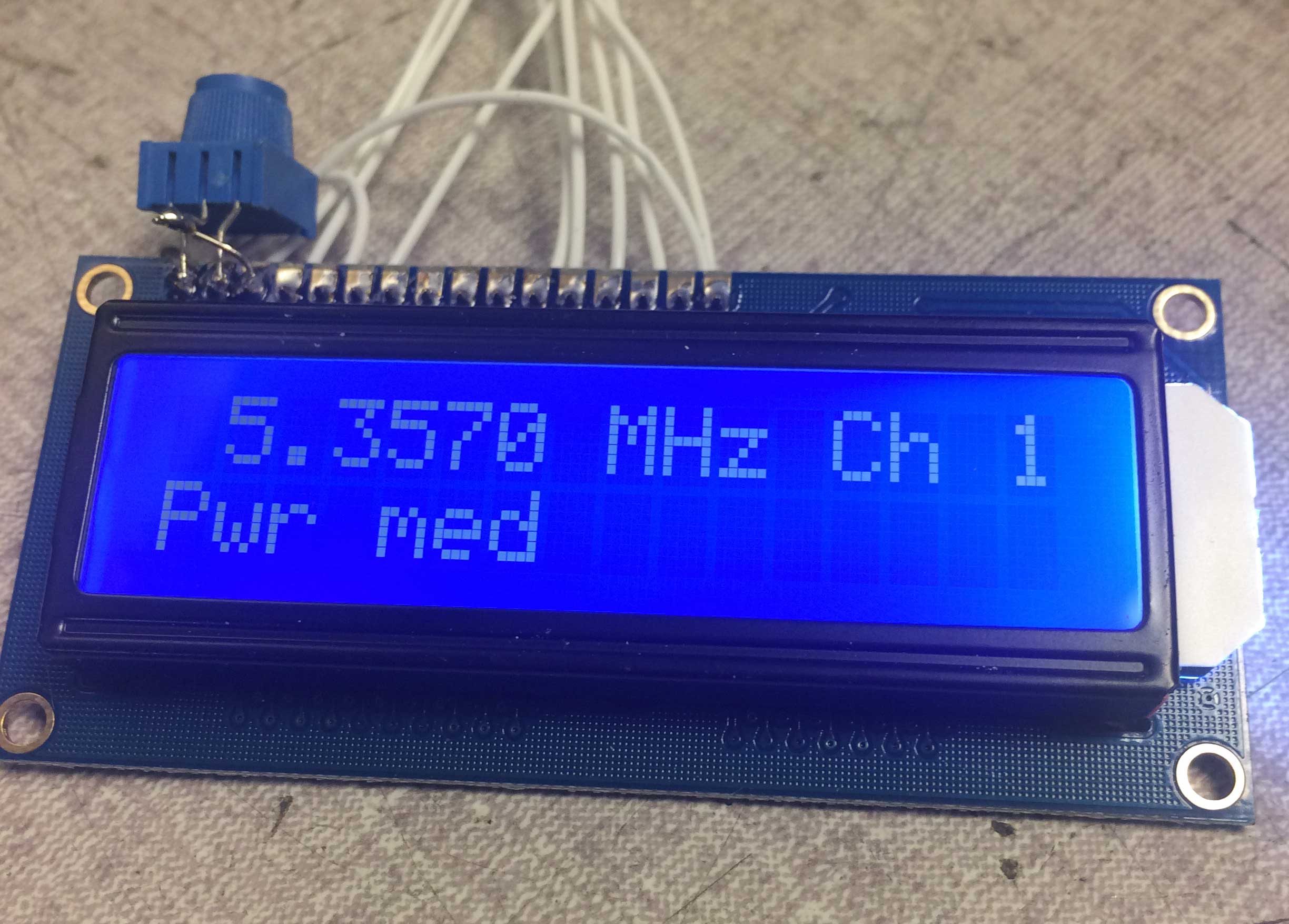
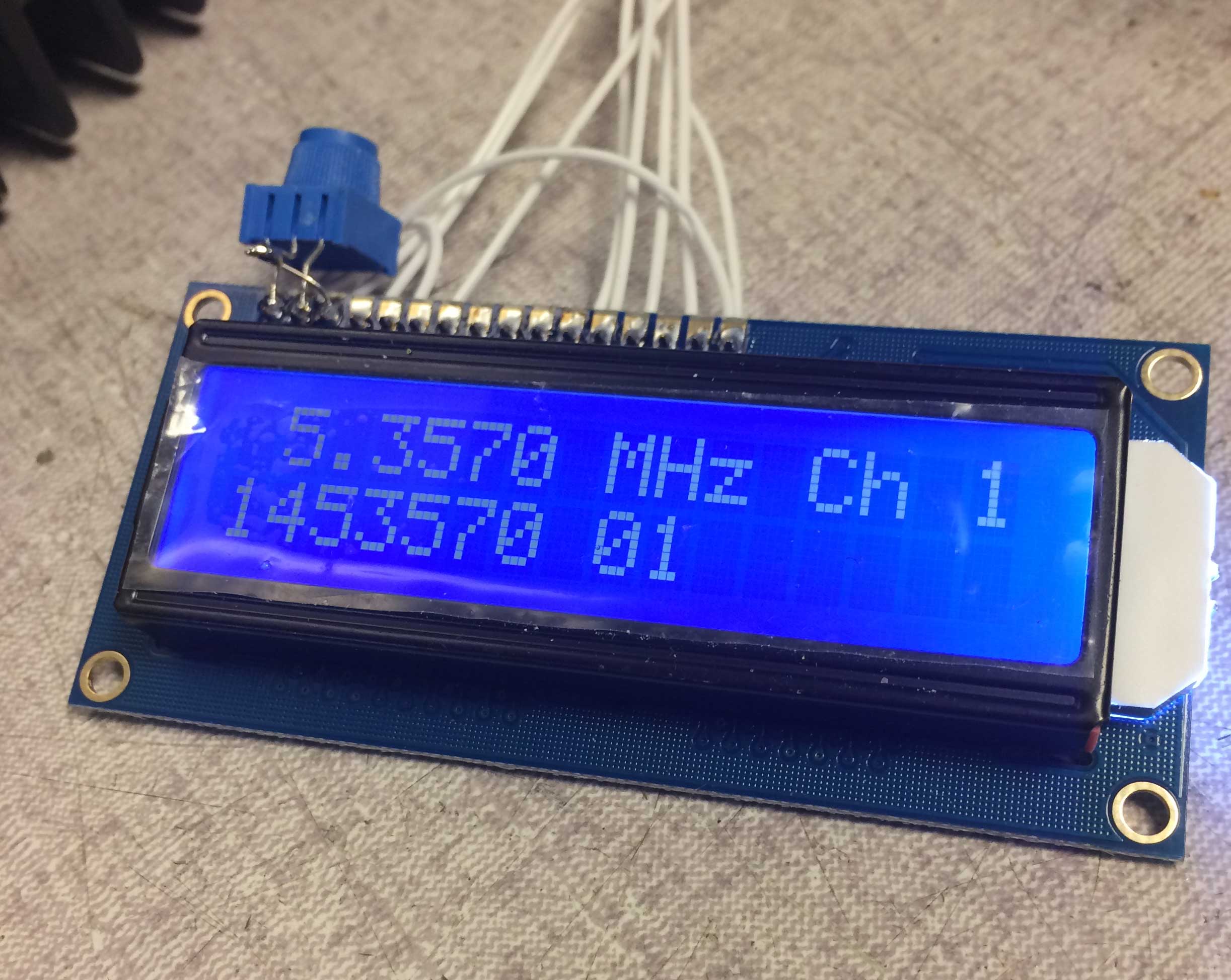
When I get into program mode some of the display data is wrong, such as channel number, so I think I have a problem in my LCD chip emulation code which I’ll have to investigate.  Well, at least the radio can be programmed now and I get a “Good” on tune.

More tomorrow.


Syncal 2000 display project, part 13

Uno to Pro Mini  transition

Up until this point I have been doing all my development and testing using the Arduino Uno, even though my plan all along was to use the Arduino Pro Mini.  Both use the same processor, run on 5 volts, and have a 16 MHz clock.  The difference is that the Pro Mini uses a surface mount part instead of through hole and eliminates the on-board USB interface.  The Mini Pro is a very tiny board and is theoretically code compatible with the larger Uno.  Nevertheless, the build definitions file used in the compiler is different and I decided to switch over to the Mini Pro for further development to make sure there weren’t any “gotchas.”  Here are a few photos showing the size comparison.

The 6 pin header on the Mini Pro (on top) has 0.1 inch spacing.  The wire is 28 AWG teflon stranded for the Mini, 26 AWG for the Uno below it.  Here is a close-up of the Mini.  The header, by the way, is for connection to the computer for programming via a FTDI USB interface.

Here is the computer interface:

That’s one of those really tiny USB mini connectors.  On the back side is a 6 pin socket to plug into the Mini.

Here is the Mini connected to the radio:

I’m using a 20 pin DIP socket as my connector so I can bring the Mini to my desktop computer to load code to it.  That socket is nearly as large as the Mini board itself.

Initially I had build and communications errors between the computer and Mini but figured out what I needed to change in the settings, which wasn’t all that difficult and pretty obvious when I went in.  I needed to change the port from COM7 to COM8 for the new device and also needed to change the target board to Mini Pro from Uno.  Then it all worked and code loaded.  Plugging it into the radio showed that it worked perfectly so it seems the two are indeed pretty compatible.

One very interesting suggestion I got was to display actual battery voltage on the screen.  I thought the on-chip A/D was 8 bits but I was wrong, it’s 10 bits, so that would give a pretty solid XX.X volt display.  If I set the full scale to 15 volts that means each LSB is 15 mV so I could almost go to XX.XX if I really wanted.  I’m not sure I can nicely fit these digits onto the screen, although I’m playing with layouts using a 5×7 basic font for this voltage, reducing the size of the existing battery bars (which are also used for transmit power indication), and moving some of the lower status row letters closer together.

Peter


Syncal 2000 display project, part 12 – question

So I’ve gotten further now with the display, trying to move various things around.  I’d like to get some feedback on the layout I have; the good, bad and ugly of it.  So here it is right now:

The leading zero on the frequency is blanked.  The space to the right of the frequency is for a left or right arrow, I haven’t coded that functionality yet.  The bottom line is what I call the status line and shows the selected channel (if channel 0, I just have “VFO”), then Lo Md or Hi power, then Rx when squelch is open, then a letter to remind me what segment of the band I’m in (none, G for General or X for Extra), then a 3 bar bargraph to indicate battery voltage in receive and transmit power in transmit.

I want thoughts on how I’ve laid it out.  There are still things that need to be done, for example the tune, good and fail messages (probably like the original display, in the frequency area for just a second or two).  Also programming.  On that the original display blinks the digit being programmed but I’m not sure how they do that as there are two different ways for the original LCD chips so I’ll have to investigate further.  I don’t really like that method and would rather just invert black/white for the digit being programmed.  I think that’s nicer.

So, should I swap the Rx and power indication?  Should it be RX instead of Rx?  I tried to get the contrast and exposure such that you could see the extent of the pixel area to show where I’m up against the edges.

I might need to do some mechanical work next as I managed to zeroize the radio (the switches do not have stops when disassembled).  I think at this junction it is safe to remove the existing LCD control chips.  Or maybe not, maybe the processor will fault out if it doesn’t get I2C bus acknowledgement in the first few seconds while the Arduino bootloader is running and my program isn’t.  It is too inconvenient to disable that while I am going through many program iterations.  Well at least I can work out how to get the display mounted into the front casting.  I refuse to use glue, maybe I will form a very thin piece of brass sheet which goes under the screws which hold the front PCB in place.  On each side it would go from the standoffs shown below to the side bracket on the LCD, where I’d use 2-56 hardware to attach the formed brackets to the LCD mounting ears.

So, comments and critiques are sought and welcome!  This is all going to be open sourced so I’d like to put out there the best I can.

Syncal 2000 display project, part 11

It is remarkable how much I forgot about C programming.  It is definitely a perishable skill.  Nevertheless, I’ve muddled through.  I won’t bore you with all the iterations it took me to get to this point, and I’m certainly not done, but I do finally have the graphics display at least displaying frequency.

Here is what it looks like in the front panel of the radio, although still wired in all over my bench:

The display with full voltage to the LED backlight is quite bright, very easily readable in bright conditions.  I plan on having it run at very very reduced brightness except when the LED backlight in the radio is called upon to be on in which case I’ll go to full brightness.

Next is getting the status info onto the lower part of the display.  I’ll have to experiment with the font to see what looks best.  I will have a line like:

Chan 5   Power M

Then in the upper right will be the left or right arrows for tuning, the lower right will be the battery/transmit power bar indicator,  and after the power indication I was thinking of a band segment indicator (X or G) as a reminder just for fun.  I’ll also get the other misc things in there somewhere like the RX indicator, but I’ll have to play to optimize the visual look of this.

For messages, they’ll use good fonts instead of partial 7 segment and for “pass” I’ll show BITE PASS in the freq area.  So, a lot more work, but I’m getting there and it looks pretty decent!

Syncal 2000 display project, part 10

I spent quite a number of hours playing with code trying to control the new graphics display.  A lot goes into getting it to run; there of course is the hardware layer, then there is the writing of the basic routines to read and write to the display, then the higher level layers of writing commands to set it up, to select pages of internal memory, and the read-modify-write routines.

My last update involved the hardware layer and I did have to make a change.  I had a lot of trouble getting the basic Arduino IDE to accept some of the more arcane timer and interrupt commands I found on the net and I ended up with weird error messages which I ended up deciding were something I didn’t want to deal with right now.  So instead I went with what I mentioned in my last post of using the standard PWM output which I could get to 1 kHz as my LCD clock.  I had to move a couple wires around but it ended up working.

I had Vanyamba’s code as a starting point but wow did the standard Arduino IDE choke on it.  Again, tons of error messages at compilation which I had no idea what to do with.  Since his structure of commands seemed reasonable, I turned his basic display class written in C++ into regular C and brought it in to my code base.  Since I am doing a very specific project I really simplified it down.  After getting everything to compile without errors, I gave the code a simple task of writing some data to the display and loaded it.

Nothing happened.  No display, nothing.  I tried changing the LCD bias, no difference.  So I went back to basics and tried the code with simple commands and looked at the Arduino pins to see if they were doing what I wanted.  I studied the LCD control chip timing diagrams and discovered there was a race condition and swapped a couple of Vanyamba’s write statements which control pins and after verifying it on the scope I hooked up the display and that did it!   I have a slightly different display than he used so that may have made the difference.  Here is what the display looks like:

All the display setup works and I initialized it by filling the memory with 0xAA characters which is a 10101010 pattern.  Alright!

I think I’m going to use a 12×16 font for the main frequency display and under it a smaller 8×8 font  for channel number, power setting, etc.  I loaded the fonts into my program and will next concentrate on the read-modify-write of LCD memory to display them where I want.  That’s for another night.


Syncal 2000 display project, part 9

The next step, going to a graphics display, is a big one.  There are several reasons for this:

  1. The display interface is 8 bit parallel with a number of control lines
  2. The display requires a 2 kHz clock signal
  3. The display controller chips are complicated to program
  4. I will be sending pixel data to the display instead of ASCII characters

So this is taking me some time.  I found some other Arduino projects on the web where this particular type of display is used, but they are rather complicated and since they are not for this exact Arduino processor, they would require a number of changes.  They are also for a C++ compiler and I’m using the very simple plain C Arduino IDE.  So much for code re-usability, it looks like I’m going to have to write my own.

In the meanwhile, some hardware notes.  My measurements worked out well and the displays I ordered fit nicely.  Here is a photo of the front of the panel with the LCD held in with my fingers.  Note I still have the blue protective film on the display.

fp-front

Here it is from the back:

fp-rear

It fits nicely!

Note on the paper behind some data.  I was playing with triggering on the I2C bus when changing mode switch positions.  With the digital scope I could read both clock and data and see what happened.  I think I have a real shot at picking up mode info from the bus and displaying it.  But that’s for later.

I’m using the Arduino Uno for development but will use the Nano for the final installation.  The Nano is VERY small!  Here is a photo of the display next to the Nano.

components

How cool is that?

Anyhow, here I am beginning to wire it up.  Those 50 mil pitch pins on the display are small to solder, and all 20 are used.

wiring

Back to the software.  The display needs a 2 kHz clock and in the example I found on GitHub (from the guy behind Vanyamba Electronics) an interrupt is used to toggle an output pin based on a timer which fires every 500 microseconds.  My experience is that these clock speed requirements are frequently not very demanding and I wondered what frequency the built in PWM ran at.  It turns out it defaults to 1 kHz and can be changed.  So my simpler solution will be to set a PWM output to 50% and get the frequency as close to 2 kHz as I can.  Voila! No dealing with interrupt coding or latency effects on the I2C slave code.  This will be the first thing I test and bring up in my step-by-step march to getting the display to work.  I can easily check that with the scope.

Probably next I will write some basic routines to send and receive data from the display.  I’ll need this of course for writing pixels, but also for reading and writing commands, setting position, etc.  The way I imagine this working is to, in sequence, toggle microprocessor output pins in the right sequence, like set CS, E, then present data to the 8 outputs, then the WR pin to write it out.  Something like that.  The data sheet for the SBN1661 chips in the display give some program sequences.  I’ll start with that and if I run into trouble see what Vanyanba did.  If I really run into trouble I’ll take out the logic analyzer to make sure I’m outputting what I think I am.  Once I can initialize the display and write pixels to it the rest will be pretty easy as I found a whole library of LCD fonts:

https://github.com/basti79/LCD-fonts

I’ll give an update when I have a little progress in coding.


Syncal 2000 display project, part 8

This is only a slight update.

The mechanical space in the front panel of the radio permit only a limited number of different models of display.  The Vishay-Dale unit I want to use which fits nicely is very new, so new that it is nearly impossible to find.  I am getting one via a connection, but also found a LCD which will fit as well.  The reason I am so constrained is that I want a large display area yet there isn’t much room around that area in the front casting.

The LCD I want to try is a Newhaven Display NHD-12232KZ-NSW-BBW-P.  I have a couple on order from Digikey.  At this point I will write the driver code to handle both types of display and show pictures of both the older technology LCD and how it looks done in the new OLED technology.

As for fonts, I found a number of ones available in open source, in different XY pixel sizes, so I will be able to have the frequency in a large font and the channel and status info in a smaller font.  I’m still playing with design ideas for layout.

Both displays aren’t expected until sometime next week, and I might be too busy the end of next week going into the weekend to get to further development.  But after that, with all the holidays and days off I will have plenty of time.

I still want to set up an Arduino as a I2C bus monitor to dump all bus transactions to the PC.  This will require rewriting the wire.h library functions to operate in either promiscuous mode or with selectable filtering while not sending the acknowledge signal back to the master.  I’d also modify it to print the bus address before each transaction data.  Why do this?  Because I’d like to be able to display radio mode and this can be read out from one of the bus expansion chips which the mode switch connects to.  Who knows what else I can find.  I could also display when the radio is in a ham band (as a reminder) and what class of license segment as well.  Stuff like that.

Syncal 2000 display project, part 7

I did a few code tweaks:

  1. Instead of calling it Channel 0, I had the display say “VFO” because that’s what it really is
  2. Added power indication to display
  3. Added the left and right arrows for tuning indication
  4. Cleared display between modes
  5. Most importantly, fixed the bug where it wouldn’t update.

img_8987 img_8988

The problem with not updating was due to my not reading in all the bytes on a receive.  One of those typical n/n-1 programming errors.  At this point I’m pretty much going to put this aside until I get the desired display.  I’ve decided to use a Vishay-Dale O128O032ALPP3N0000 OLED unit.  It’s 128×32 pixels and I’m going to need to find some decent font to use for it.  I’ve heard those can be found on the net.  I’d like the frequency to be reasonably large and the status etc can be smaller and off to the sides.  This isn’t a perfect display as it’s smaller than the window, but it’s a standard part and the larger ones won’t fit in the radio mechanically.  This will change as a lot more are being made as the OLED ones replace the older LCD types.

Interestingly, the display doesn’t show operating mode.  I’m investigating whether I can intercept the switch status from the I2C bus and then display it.


Syncal 2000 display project, part 6

Alright, spent a bunch of hours coding.  As typical of coding, some things went easy, some were worthy of tearing my hair out over.  I finished and tested the LCD driver chip emulation including indexing and loading actual display data to an array.  I also wrote and debugged the subroutine to recognize both number and letter data from the individual 7 segment signals and turn it back into numbers and letters (some is not possible, such as “5” vs “S”).

I finally had enough for the day and called it quits.  I am now able to read out and display the radio frequency and channel like this:

img_8970b

The bottom line is some diagnostic info I no longer need.  This is a big deal!  With all the command and data properly read out, most of the hard part is already behind me now.

One weird thing though, and I have no idea what’s up.  Previous to today, the data receive routine would update on each packet received.  But now, it only runs once.  It runs properly, but only once!  I tried commenting out large sections of code to no avail.  I may have to post my code to Stack Exchange and ask if anyone has encountered this before or has any hints.  I don’t mind posting it since I will open source it to GitHub when I’m done anyway.  I don’t think my rusty coding will be too embarrassing, ha ha.

While attempting to debug this problem I put statements which turned on and off an output pin so I could observe it on a scope.  This also allowed me to time certain sections of code, and I was curious about how fast the C code ran.  It turns out, respectably fast: my command decoder and data retriever, dozens and dozens of instructions, takes a grand total of 62 microseconds to execute.  As for size, with the libraries my code right now stands at about 15% of the available space on the chip.  Not too bad, these parts have pretty decent capability both in speed and size of program you can fit into them.


Syncal 2000 display project, part 5

Some interesting data.  I placed the old LCD against the zebra pads and realized that there was another item initially displayed, a “PASS” indication.  I took a video of my Arduino LCD as the radio powered up and say this which happened just before that “PASS” indication:

display-pass

Ok, so what does it mean?

E1     LCD chip device select 1
E0     LCD chip device select 0
C9     Mode set:  static, normal, enabled, bias set
F8     RAM bank select:  Bit 0 for both loading and display
F0     Blink mode:  normal, off

Segment mapping is using the standard 7 segment A-G pattern:
00     10 MHz:  blank
00     1 MHz:  blank
CE     100 kHz:  “P”
EE     10 kHz:  “A”
B6     1 kHz:  “S”
B6     100 Hz:  “S”
00      Ch 10:  blank
00      Ch 1:  blank

Well, it does seem not all display writes have 16 bytes, and I’m not sure why some were missing from the first line, perhaps the Arduino is reading them faster than they are coming in, that doesn’t make any sense but in any case the above decoding makes perfect sense.  I also captured a full data display in operation but will save decoding that for a later time, if it proves necessary or helpful.

So there it is!  I’ve established:
1:  The Arduino can read addr 57 I2C data from the Syncal 2000 radio control data bus
2:  The status words being written to the LCD control chips make sense
3:  My reverse engineering of the segments to loaded data make sense

Enough for tonight.  Tomorrow we will go out but when I’m in later I will write some rudimentary code to interpret the data and write the radio frequency to the Arduino LCD display.

Things are moving quickly so I will also take final mechanical measurements and order the OLED display which best fits in the radio display available space.  By the time it arrives I should be far enough along that I will have most original display elements written to variables and can start on creating a visually appealing OLED graphic display.

Peter